Navtelecom
Model
🚩
Problem: Suppose you have a transportation monitoring tracker connected to a scooter and running Navtelecom protocol. It is known to transmit the following parameters.
| Parameter | Parameter number in the protocol | FLEX |
|---|---|---|
| Event code | 2 | 1.0 |
| Event Time | 3 | 1.0 |
| Status of function modules 1 | 5 | 1.0 |
| Status of Functional Modules 2 | 6 | 1.0 |
| GSM Level | 7 | 1.0 |
| Number of satellites | 8 | 1.0 |
| Navigation receiver enabled | 8 | 1.0 |
| Valid navigation | 8 | 1.0 |
| Latitude | 10 | 1.0 |
| Longitude | 11 | 1.0 |
| Speed | 13 | 1.0 |
| Course | 14 1.0 | 1.0 |
| Mileage | 15 | 1.0 |
| Battery voltage | 20 | 1.0 |
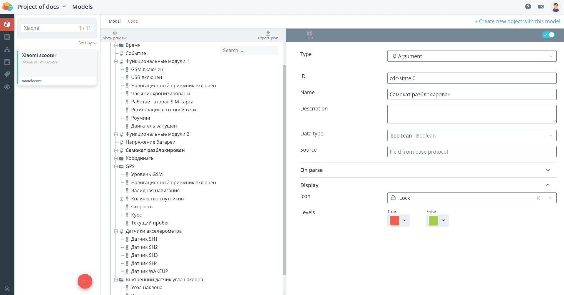
| Scooter unlocked | 31, 1st output | 1.0 |
| Status of virtual accelerometer sensors | 139 | 3.0 |
| Tilt angle relative to local vertical | 140 | 3.0 |
| Pitch angle | 141 | 3.0 |
| Roll angle | 141 | 3.0 |
🚩
Also, the description of the tracker says that it provides a response to the following commands.
| Command | Description |
|---|---|
| Request device model and version | System command |
| Request firmware information | System command |
| Unlock | Enable output 1 |
| Lock | Disable output 1 |
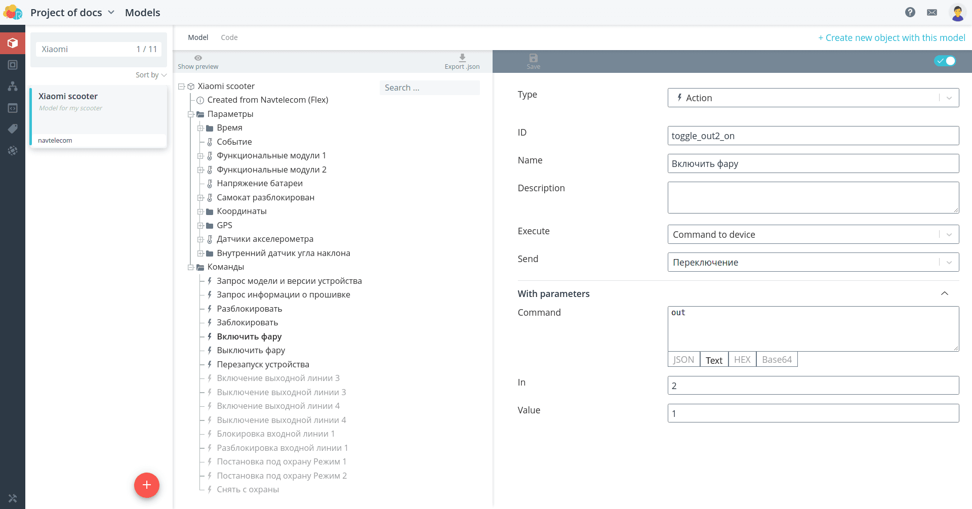
| Turn on headlight | Enable output 2 |
| Turn off headlight | Disable output 2 |
| Restart the device | System command |
To connect the scooter tracker to the platform, create a model for it.
Navtelecom.
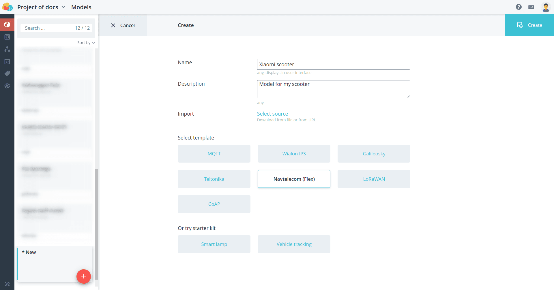
The template model has all the parameters from the FLEX 1.0, 2.0 protocol sections and
some parameters from the FLEX 3.0 section. By searching the template model you can
to see which parameters are already present and which ones you need to add yourself.
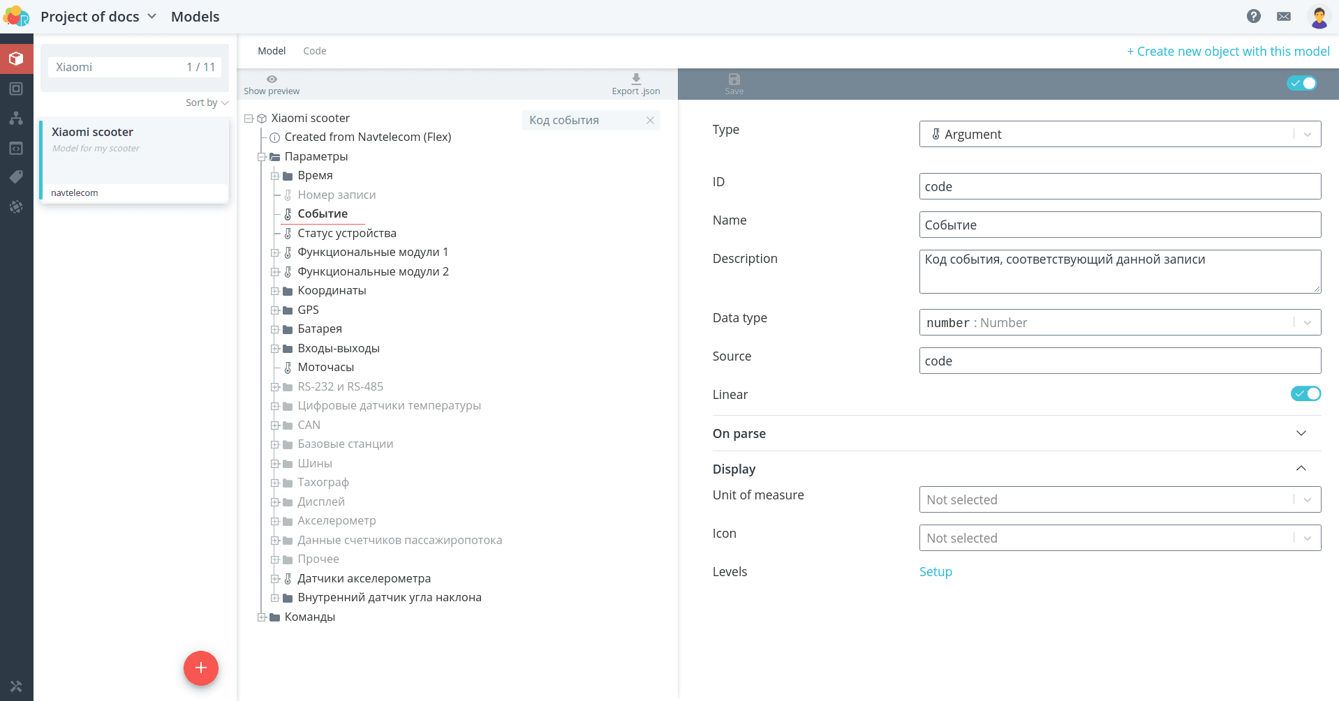
In this case, all the necessary parameters are already present in the model. It remains
only to remove or hide unnecessary parameters from display, and the necessary parameters
group them.
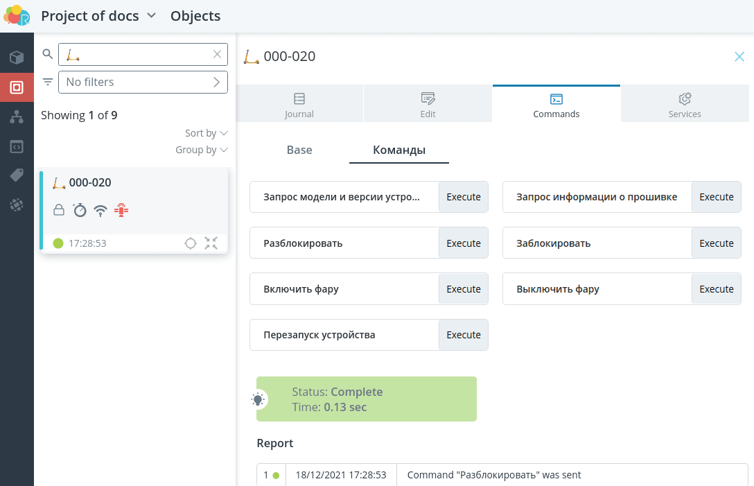
Also, all possible commands that can be sent are predefined in the template model.
The commands to turn output line 1 on and off are in this case responsible for
locking the scooter, and output line 2 is responsible for the headlight. Rename these commands.
Other necessary commands can be left unchanged, and any unnecessary actions can be
can be removed or hidden from the display.
View a preview of the object with the model you created by clicking the Show preview button.
preview**.
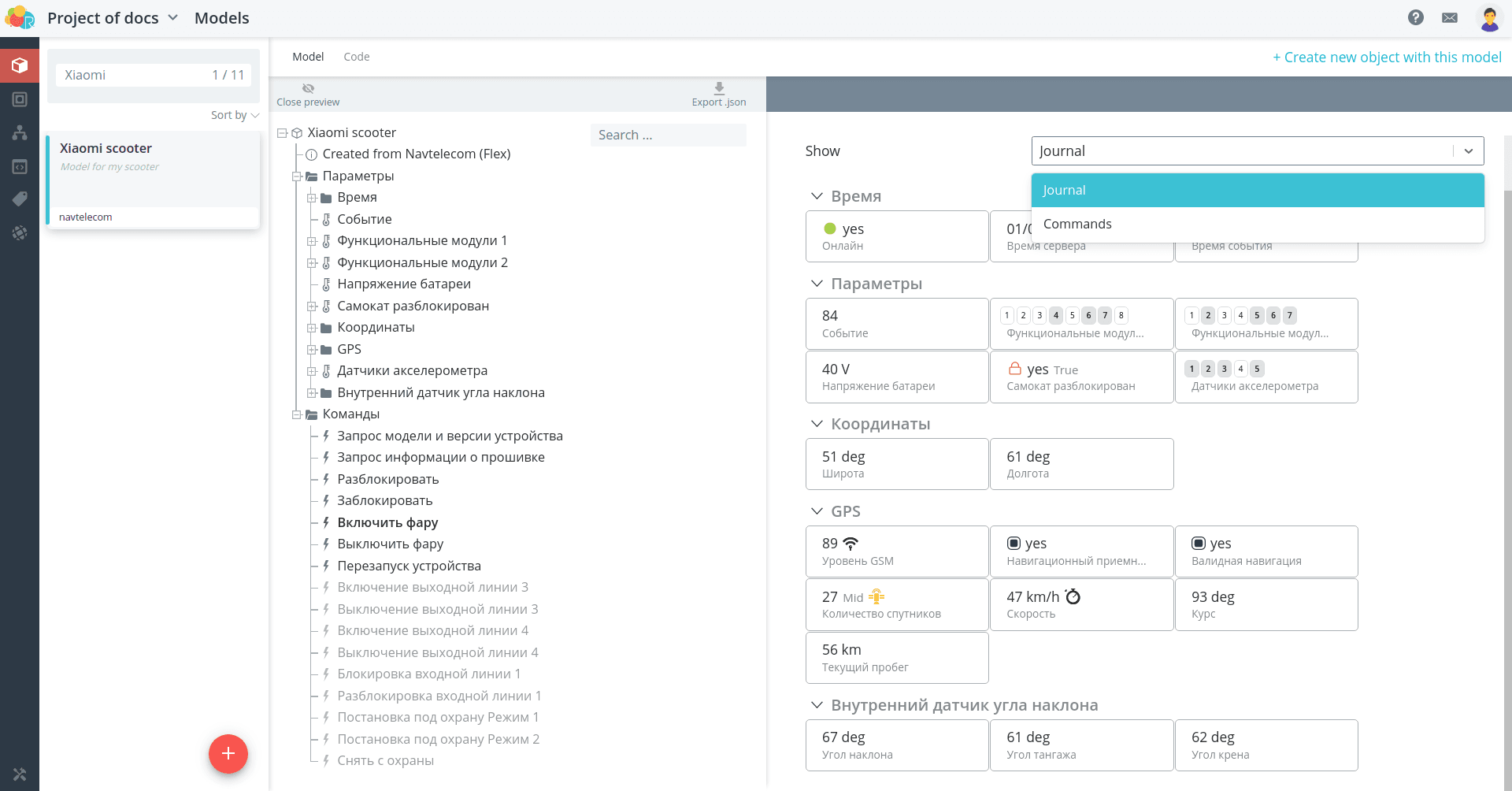
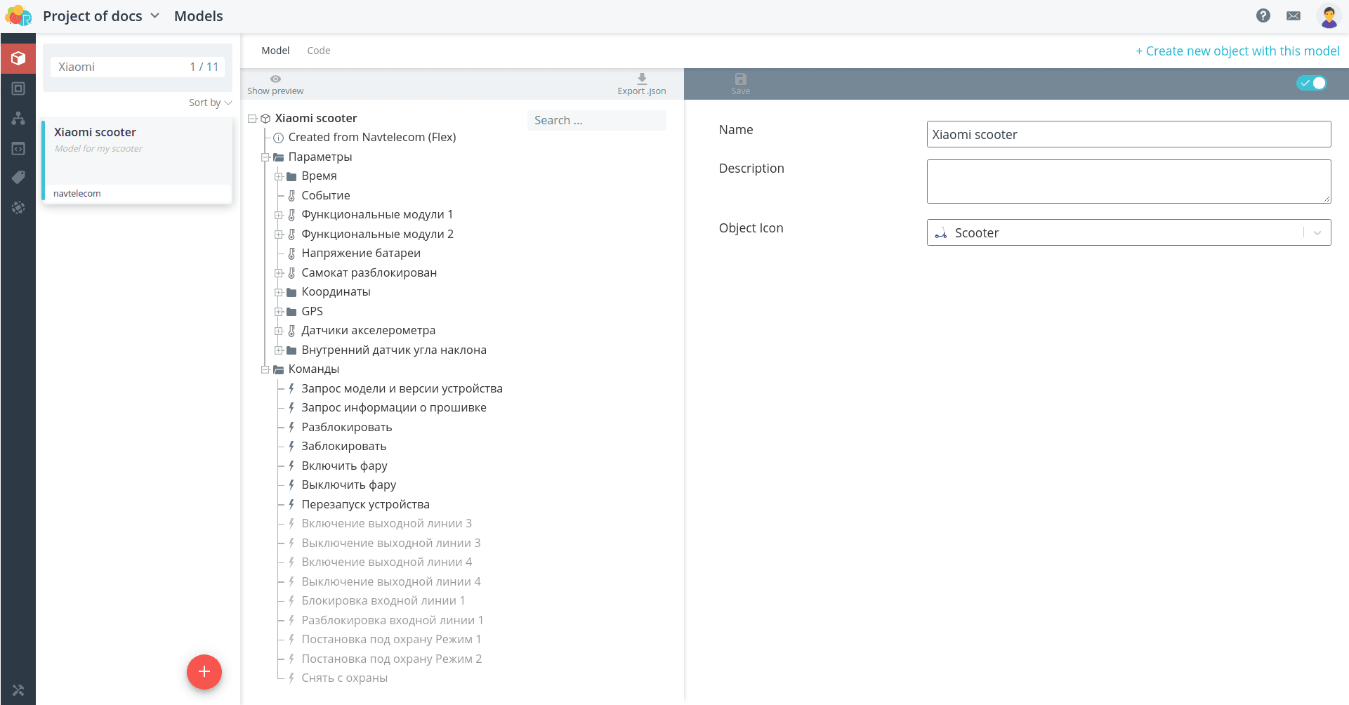
If you wish, select an icon to display the object on the map, or upload your own
image.
Object
Create an object for your scooter. Select the model you just
created. Then enter the ID that corresponds to the IMEI of the monitoring unit,
** prefixed with ntcb:**. Specify a name for the object.
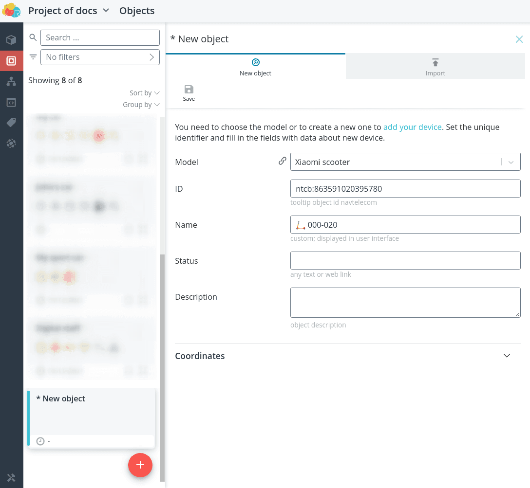
Once saved, the instructions for configuring the device to the platform will open.
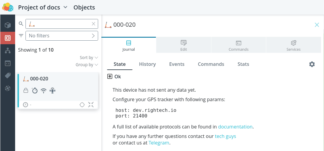
Connection
To connect the scooter to the platform in the configurator settings of the block
monitor unit configurator settings
- host dev.rightech.io
- port 21400
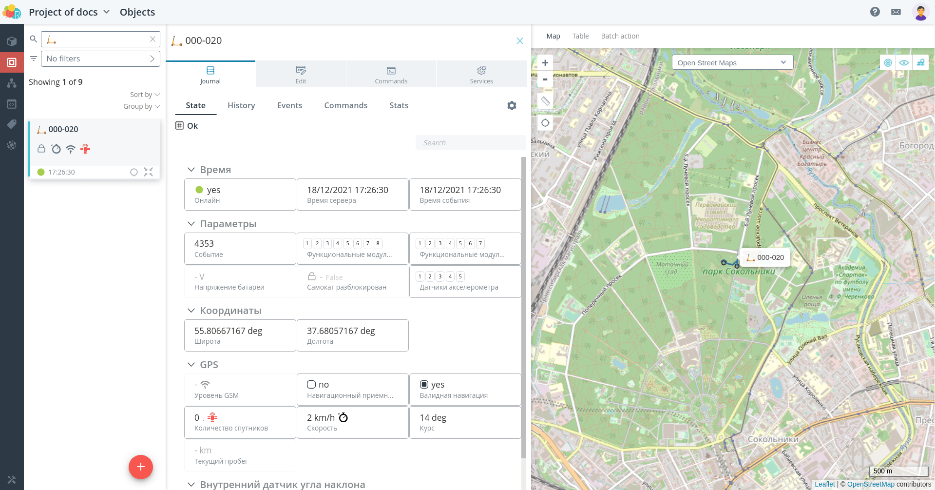
Make sure that after saving the settings, data from the device is sent and
are displayed in the interface. After receiving the coordinate packet, the object should
be displayed on the map.
Send commands and check that the connected device responds to them.
Logic
As an example on complex geo-fence control, consider the following task.
🚩
Task: Suppose we need to send different notifications to the platform if a scooter has left a valid geo-zone for riding and if the scooter has entered a geo-zone that is strictly forbidden for riding. It turns out that in this example there are two geofences over which the scooter movement control is different.
The automaton will contain three states:
-
pending event triggering on geo-fence crossing;
-
outside the authorized geofence;
-
in a forbidden geofence.
Transitions between these states will occur when we receive the events of entry and
exit events from the corresponding geozones. However, if in
one of the past examples
default events Entry/exit geofence were used, in this case you need to add your own events to the model.
In this case you need to add your own events to the model, which will then be used to make transitions in the automaton.
transitions in the automaton. If you don't do this and use the default events
default events, then, for example, the Geozone Exit event will be triggered when you exit from an authorized geofence.
exit from both allowed and forbidden geofences, and you will not be able to distinguish between them in the automaton.
to distinguish between the two in the automaton.
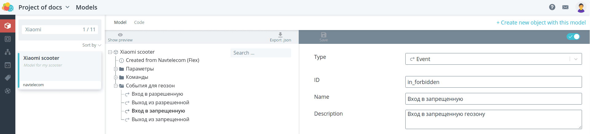
Go to the model and create additional events. You need to create at least
at least two events: leaving the allowed geofence and entering the forbidden geofence.
However, it is better to create a complete set of events for both types of geo-fences, i.e.
four events.
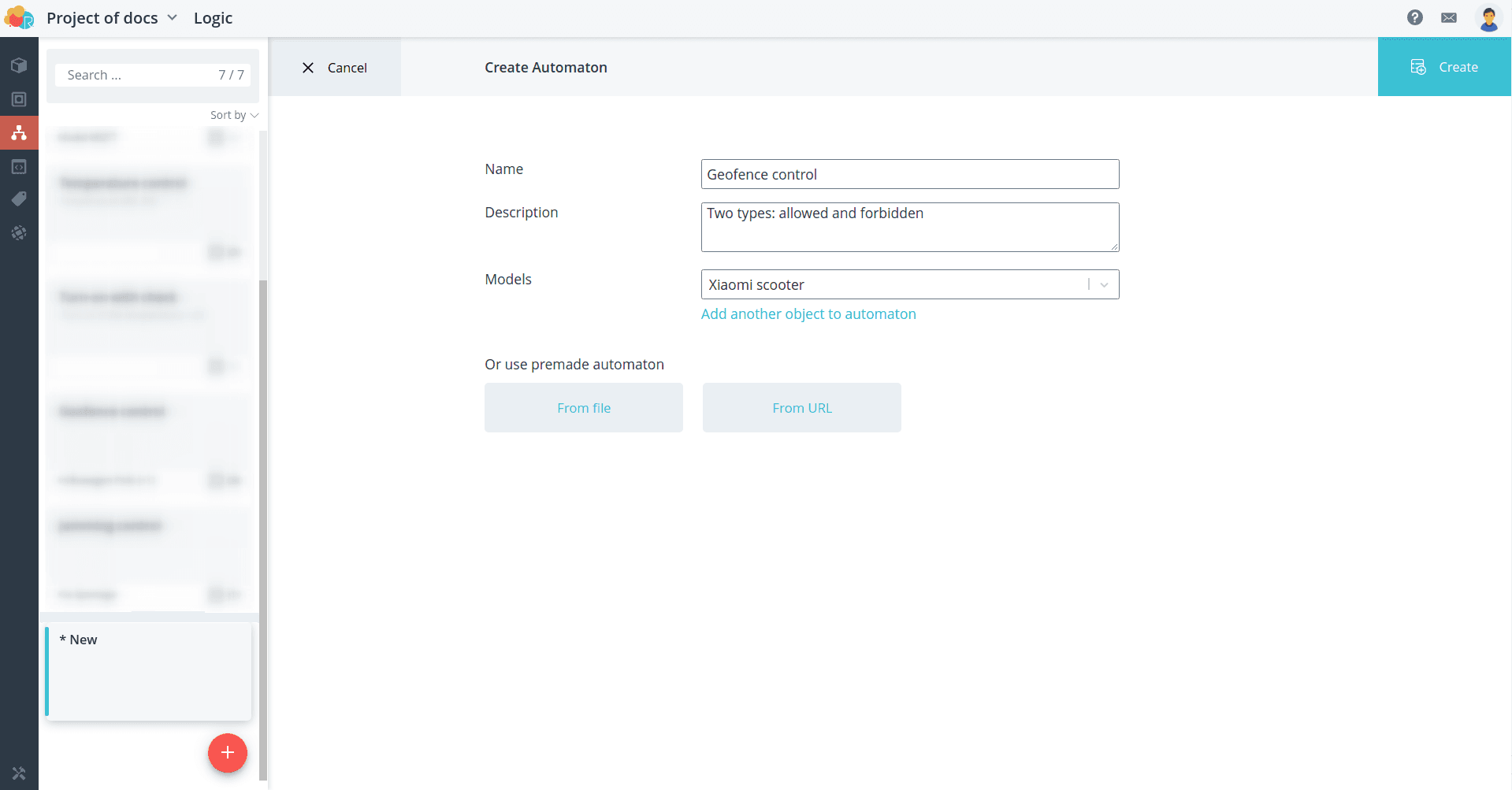
Create a new automaton.
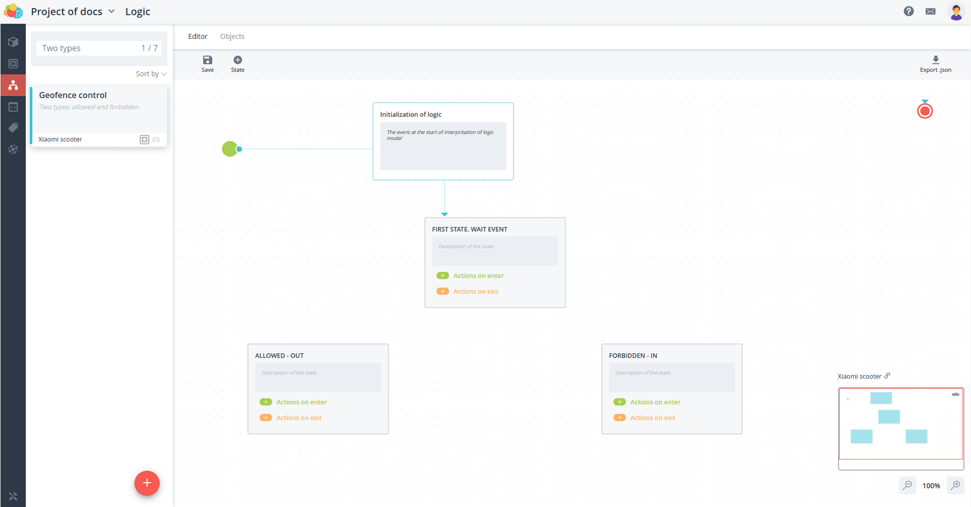
Since the logic of the automation script calls for cyclic
control of entering and leaving geofences, the automaton will be infinite, the final
state can be moved out of sight and not
use. Create three states of the automaton.

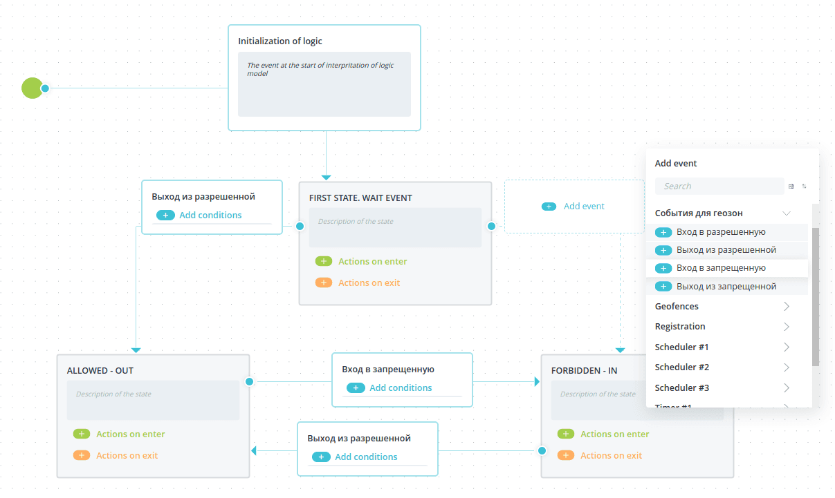
Transitions between states will occur when events are received about entering or
exit from the geofence. No additional conditions need to be checked in this case.
Note that you should select the events you created, not the events for geofences present in the geofence.
not the default geofence events.
Now add commands to send notifications.
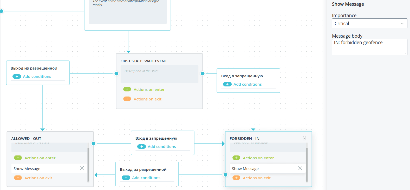
The automaton is ready. Select the scooter object and run it.
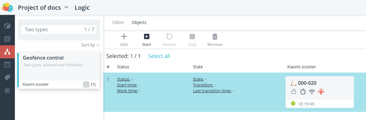
The automaton is running, but events must be received to transition between states
of entering and exiting controlled geo-zones.
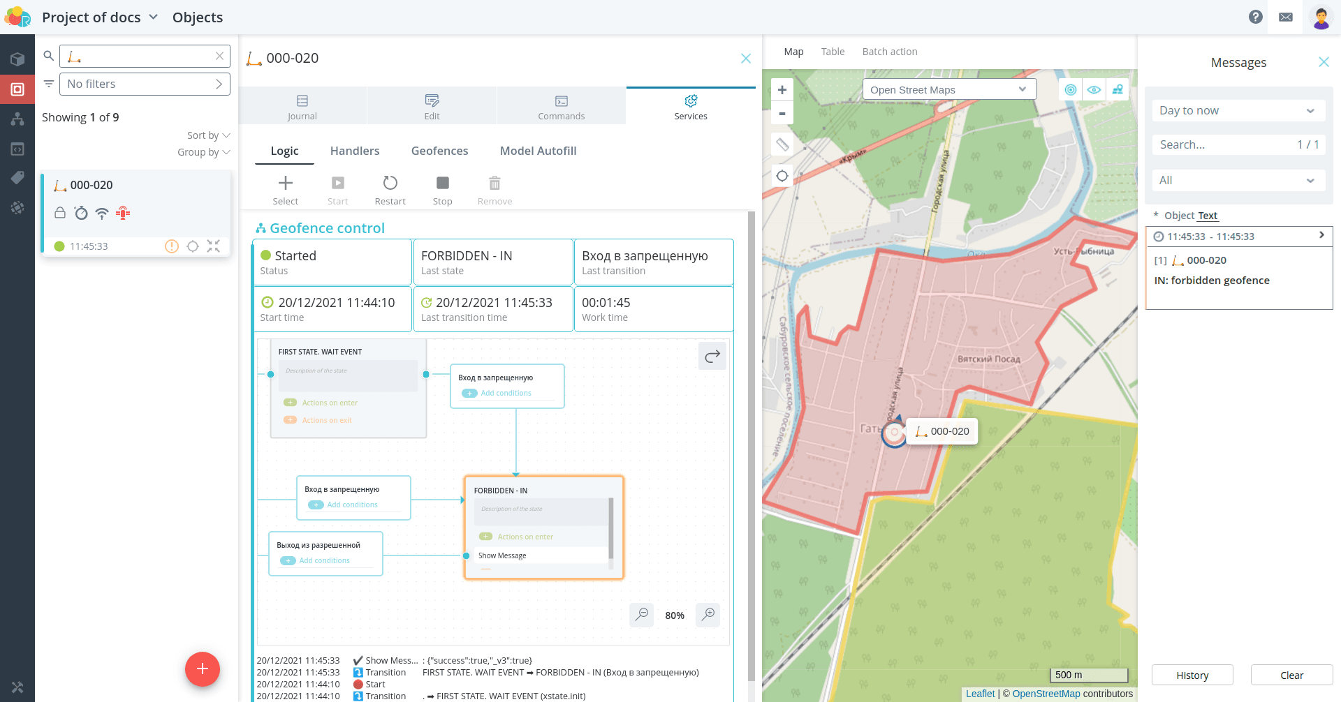
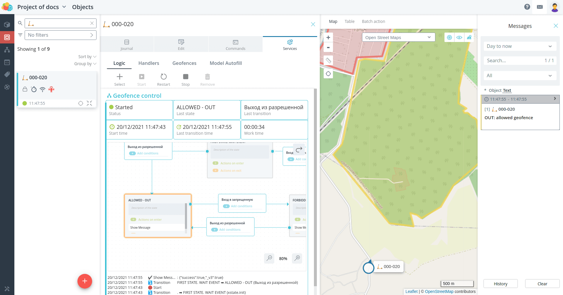
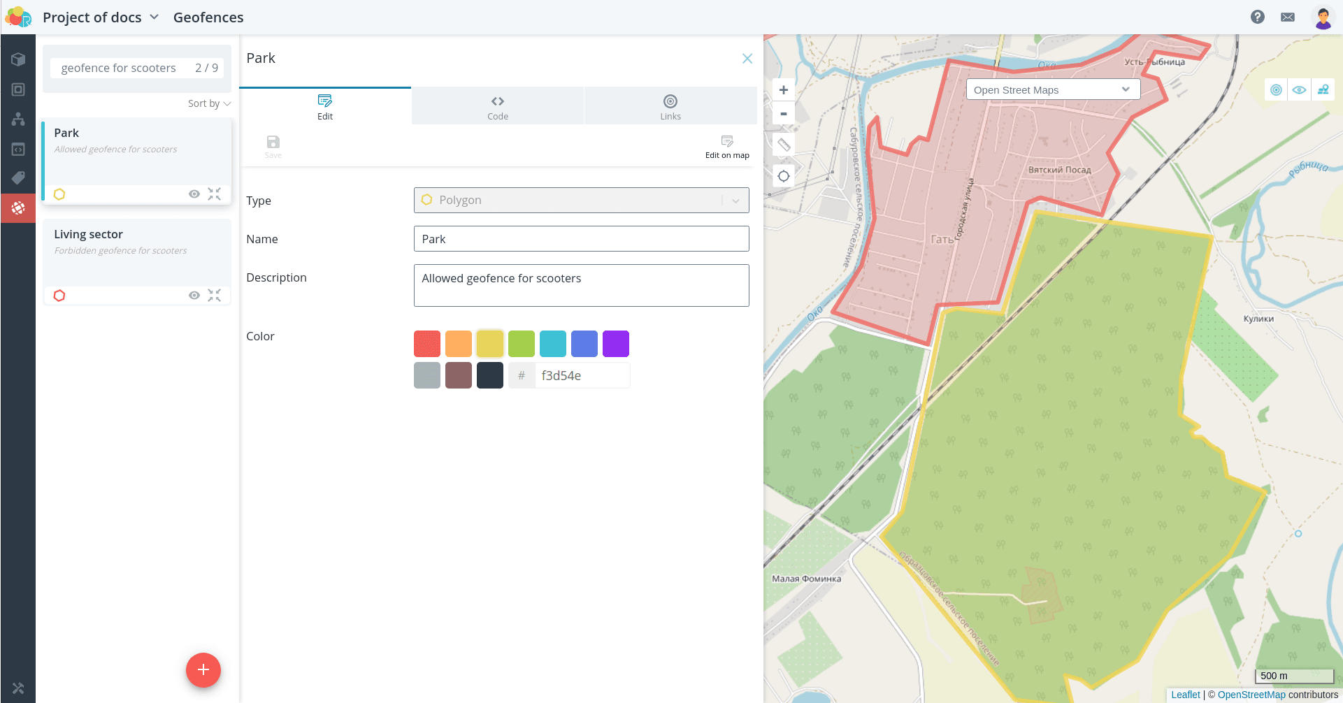
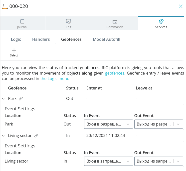
Geofences
Create geofences that define the allowed and forbidden area for the
scooter use.
Add geofences to the scooter object. After receiving the actual coordinates
the status of being in the In/Out geofences will appear.
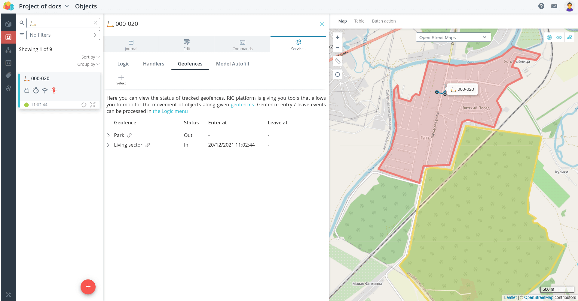
Add the appropriate events for these geofences that you created earlier.
Then they will be generated when you enter and exit the geofence. These are the ones
used in the automaton.
Now when entering and exiting geofences there is a transition between states and the
notifications are sent.