Creating a device model
To create a new model, click on the Models tab. Add a model
by clicking on the plus sign.
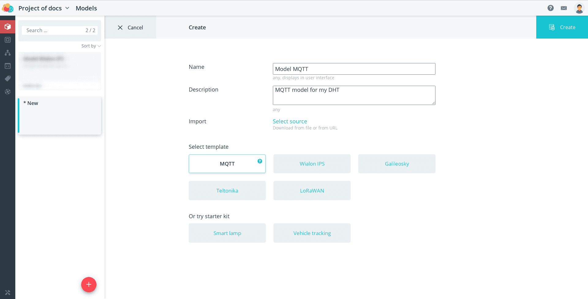
Fill in the following fields:
- name - model name;
- description - detailed description of the model, to be filled in if necessary;
- import - possibility to import ready model as a file or by link.
Select a template - prepared model structure. Added to the platform
several ready-made models created on the basis of the protocols implemented in it.
The model is created based on the selected template and includes a number of arguments, events
and actions that can be used for devices with that protocol. You
only need to customize the model by adding, removing, and configuring model nodes.
Alternatively, instead of creating a new model, you can use one of the starter
kits.
Read more about starter kits
Read more about starter kits
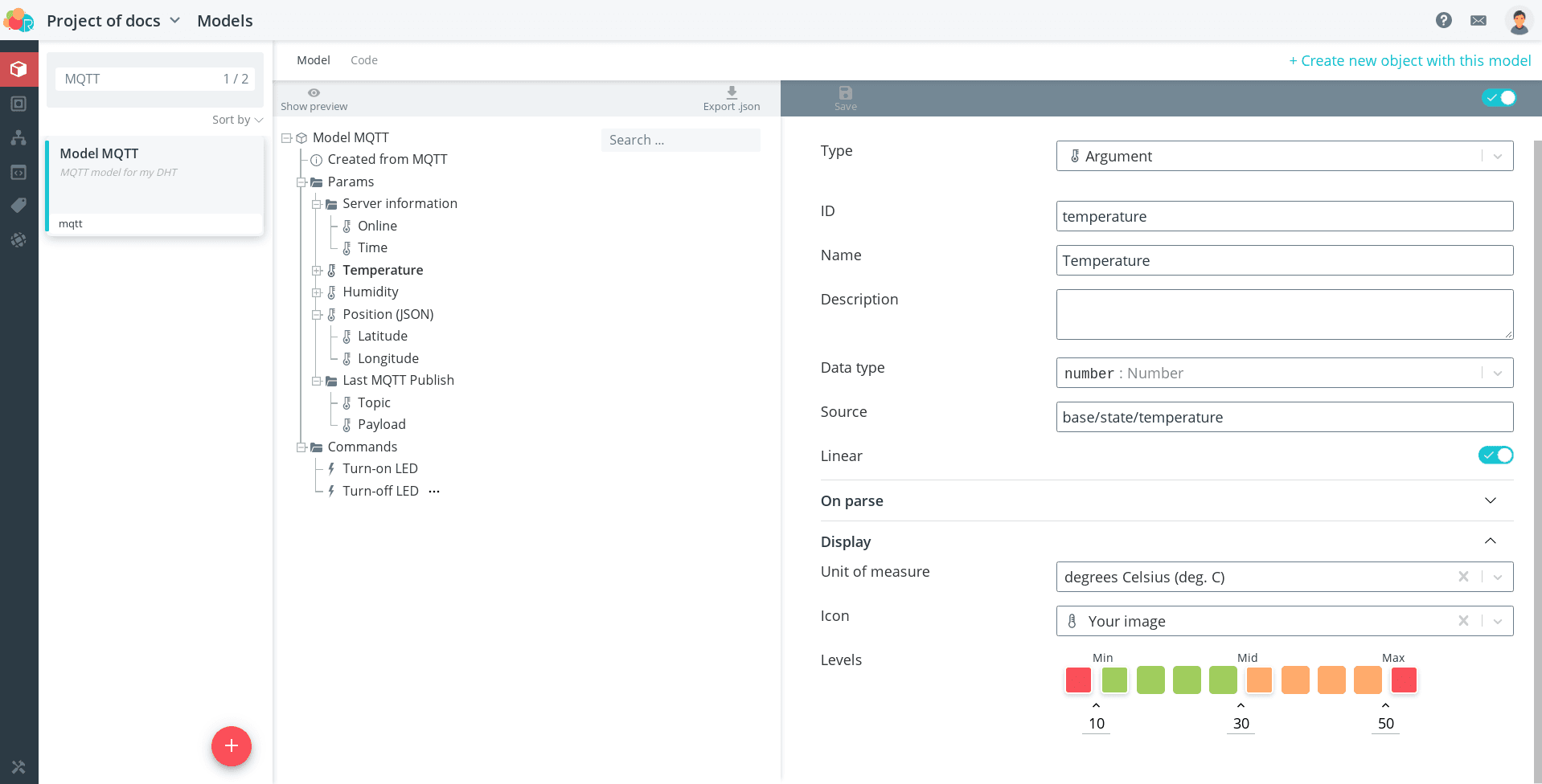
Click the Create button. Your new model will open in front of you. On the left
part displays the tree structure of the model, which includes different types of nodes.
nodes. The right side shows the edit window for the selected node.
Parameters of model nodes
Common
First, each node specifies its type. Depending on the selected type
the corresponding form fields are formed for further filling.
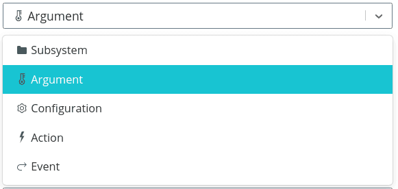
Types:
-
Subsystem - node type, which serves to organize the model structure, allowing to combine parameters into groups. Subsystem implies that this node contains several elements in the form of branches of the tree structure. structure.
-
Argument is a parameter that the device passes to the platform (e.g., the current sensor measurement).
Arguments can be numeric, boolean, string, or represent an object or array. array. For numeric arguments, you can specify the unit of measurement, image, and levels. -
Configuration is a parameter, the value of which can then be set in the object's interface of the object. It can be used in automata and handlers. In essence, nodes with this type are constants, which are needed to storing additional information about the object. It can be, for example, maximum allowable temperature, fuel tank volume, duration of operation, etc. etc.
-
Action is an operation that is needed to send a command to a device or to start the dispenser.
-
Event is the occurrence of certain conditions that either have been recorded by the object or occurred in applications external to the object. control applications. Events are used in automata when constructing transitions between states. It is on the basis of events that have occurred to the object that these transitions occur.
💡
Each type has an icon that appears to the left of the node in the tree of the
Model. This allows you to visually identify which type a particular node
belongs to. to which type a node belongs.
Next, a model-unique identifier and name of the node are entered.
The identifier is needed to recognize the node in the system. It is the name
field from the device state data when accessing it via API. The name, unlike the identifier.
unlike the identifier, the name can be non-unique. Both the identifier and the name
are generated when the node is created, they should be replaced with the identifier and name,
that you understand and are comfortable with.
💡
The identifier must be unique! The identifier must be meaningful! The
identifier is for the inner workings of the system, the name is for the
interface of the user.
The platform also includes additional functions for arguments with special
identifiers.
| Parameter ID | Function | |
|---|---|---|
| System information, always present in the object interface | ||
| online | Device connection status:
| |
| _ts | Time to receive the data packet from the device (stored in microseconds UTC). If the parameter with the identifier time is not used in the model, its functions are performed by _ts. its functions are performed by _ts | |
| Parameters that the user creates | ||
| time | The time by which data packets from the device in the history are sorted, may be different from the time of receipt (_ts). Often used when the device sends historical data in parallel with the actual information data | |
| lat, lon | The coordinates of moving the object on the map | |
| angle | Angle of rotation of the object icon on the map | |
| x, y, z | Ordinates of moving the object on the scheme | |
| speed | Speed of moving the object on the map when using the route for the bot | |
💡
Come up with clear and concise names. If details are needed, add a detailed
description.
Description gives a more complete picture of the parameter. It is displayed as a
as a tooltip when hovering over the parameter in the object interface.
For nodes with types "Subsystem" and "Event" no other fields need to be filled in.
The description of fields for nodes with other types is presented below.
For the "Argument" type
The following fields are populated for the argument:
-
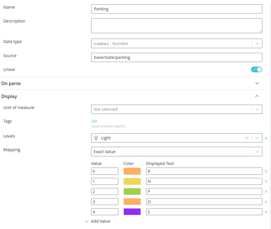
data type: one of the possible data types is selected: numeric, logical, string, object or array. The data type is used for correct display of parameter values in the interface. Also for certain types there are additional options for certain types:
-
numeric: specifying multiplier, unit, image and levels of transition levels (sections Parse and Display);
-
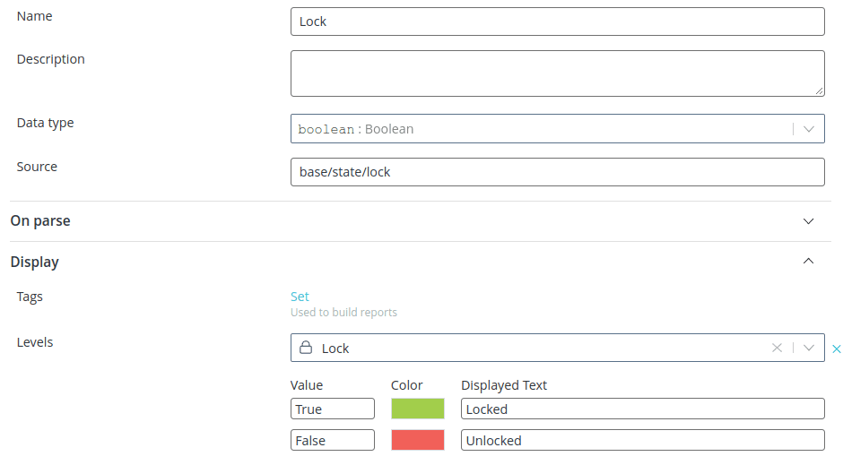
logical: specifying image and transition levels (sections Parsing and Display and Display);
-
object: parsing data in JSON format (example).
-
-
source: it is used to search for the parameter value in the data structure, received from the device; strictly protocol dependent. Configuration sources for specific protocols is described in detail in examples section;
-
linear: this switch determines whether a linear plot (smoothly increasing or smoothly increasing or smoothly decreasing) can be made on the parameter linear graph (smoothly increasing or smoothly decreasing) for a parameter: for example, you can plot a linear graph for temperature or latitude. temperature, but not latitude or longitude, such a graph for a separate coordinate is meaningless. coordinate does not make sense. When this flag is activated, it becomes available adding an image as an icon of this parameter and specifying the levels of indication levels of the current parameter value.
The Parse and Display sections open additional fields:
-
Multiplier: the parameter received from the device will be multiplied by the specified value. value (the function is only available for numbers);
-
save binary as: serves to display the data in the object interface in a different format (e.g. Text - "ok", Base64 - "b2s=", HEX - "6F 6B");
-
Unit of measure: to display next to a number; the following units have an additional function the following units of measure have an additional function:
-
percent (%) - the number is placed in a scale filled according to the received percent value;
-
milliseconds (ms) - the number obtained in UNIX milliseconds is converted to a readable date and time format. readable date and time format.
-
-
image: svg icon for additional indication, represents the parameter graphically on the object card. parameter graphically on the object card;
-
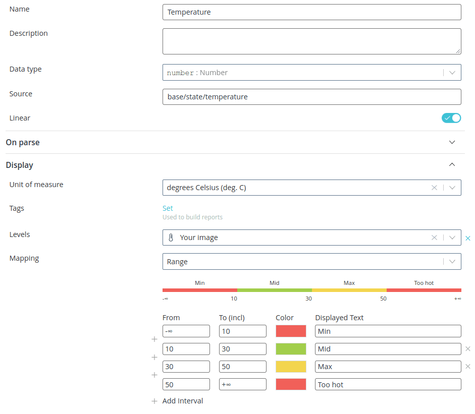
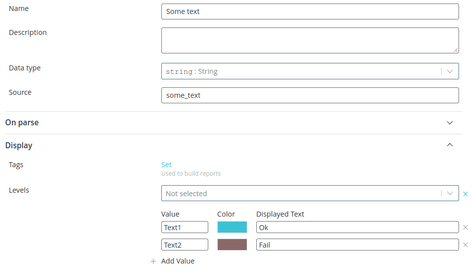
levels: thresholds for icon and text color change.
The setting of levels differs for arguments by data type:
-
number
-
change of level when the received value falls within a certain range of values values
-
level change when the received value exactly coincides with the specified value value
-
-
logic type
- string
💡
Sometimes after loading a custom SVG image, its color doesn't change according
to the set levels. according to the levels you set. In this case, open the
image with any text editor and remove the "fill" field. After that, load the
updated SVG image again. Now its color will change according to specified
levels.
For the "Configuration" type
Only the Data Type field is populated for the configuration.
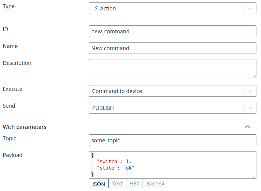
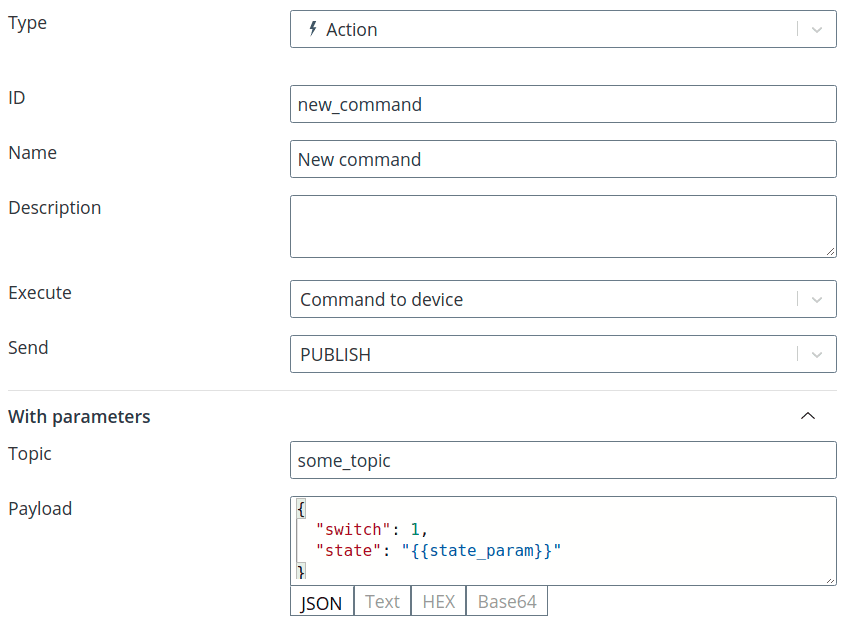
For "Action" type
For an action, the execute field is populated: select the type of action that
should be performed:
-
automation: in the Automation field, select the automaton that you want to run on command;
-
command to device: in the Send field select the type of command depending on the protocol. depending on the protocol, and then in the With parameters section specify command parameters.
In the command parameters, you can specify:
- specific values that will be sent each time in the command;
- parameters whose value can be specified directly when sending the
command. This is necessary if the user does not know in advance the values which
should be sent in the command, or these values may change from time to time.
change. To create such a parameter it is necessary to declare it in curly brackets when creating a command in the
model, declare it in curly brackets
{{{param_name}};
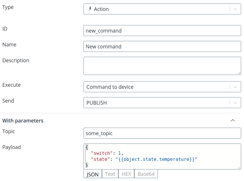
- current device parameters. To create such a parameter it is necessary when
when creating a command in the model, specify object.state in curly brackets and after the
dot specify the identifier of the parameter from the model (for example,
{{{object.state.temperature}}). When the command is sent, the value of this parameter from the log.
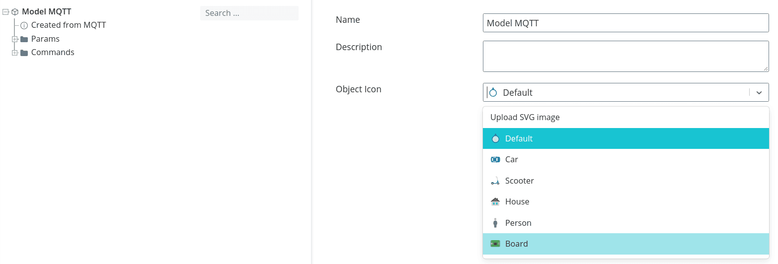
For the root node
For the root node of a model, you can set an icon in addition to the name and description. All
objects with such a model will be displayed on the map with the specified icon. In this case you can
use both standard icons and upload your own image in SVG format.
SVG format.
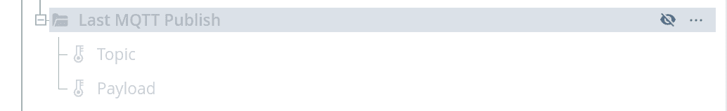
Model Structure Formation
To the right of each node of the model when pointing, an "eye" icon and three
dots, which, when clicked, open functions for working with nodes.
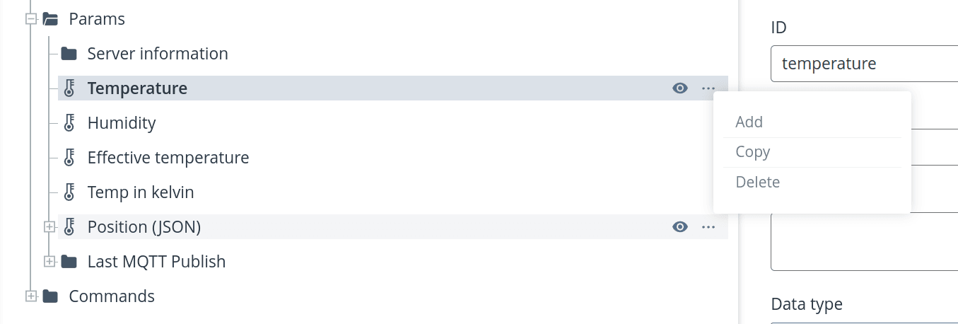
- Hide (eye icon) - hides the element from the object interface. This parameter will not be processed by the platform and displayed in the log, but it can be returned when if necessary, it can be returned. In case of hiding a node with the type Subsystem parameters, which are included in it, are also hidden in the object interface;
-
Add - creates a new node as a branch for the selected element to the level below;
-
Copy - copy the selected element. In this case, all information filled in for the node with the difference that the identifier has the generated post identifier is assigned with the generated postfix, and the name is labeled with the inscription "(copy)";
-
Delete - deletes the selected element.
All elements on the model are moved by drag-and-drop. This is how you define
the model structure for your device in a convenient way.
💡
We recommend to organize all parameters and commands into semantic groups -
subsystems. This will allow you to organize a convenient display interface in
the object.
To see what the object state and command sending interface will look like in the log, click Show Preview.
💡
Also, any model element can be edited and viewed on the Code tab. The full
structure of the model is presented there in JSON format.