Creating a scenario
To create a new automation scenario, open the Scenarios tab and click the plus icon.
Fill in the following fields:
- Name – the scenario name;
- Description – a detailed description of the scenario (optional).
Next, select the scenario type:
- By cross-elements – this type of scenario uses cross-elements, which are abstract parameters that can be created directly within the scenario without being tied to a specific model. A scenario based on cross-elements is a reusable component that can be applied to objects with different models, after mapping the cross-elements and parameters from the model of the object on which the scenario will be launched;
- By parameters from model – this type of scenario is based on a specific selected model. If the scenario involves interaction between multiple objects, select the models that correspond to those objects.
💡
Previously, all scenarios were tightly coupled to a specific model. Over time, this approach proved limiting
because it led to large numbers of nearly identical solutions and made projects harder to maintain and expand.
Cross-elements are now the primary mechanism for building scenarios. Creating automation scenarios of the
By parameters from model type is officially considered deprecated, but it remains temporarily supported for backward
compatibility.
You can also import an existing scenario from a file or via a link.

Click Create. A new scenario will open, displaying with a minimal set of elements in the workspace.
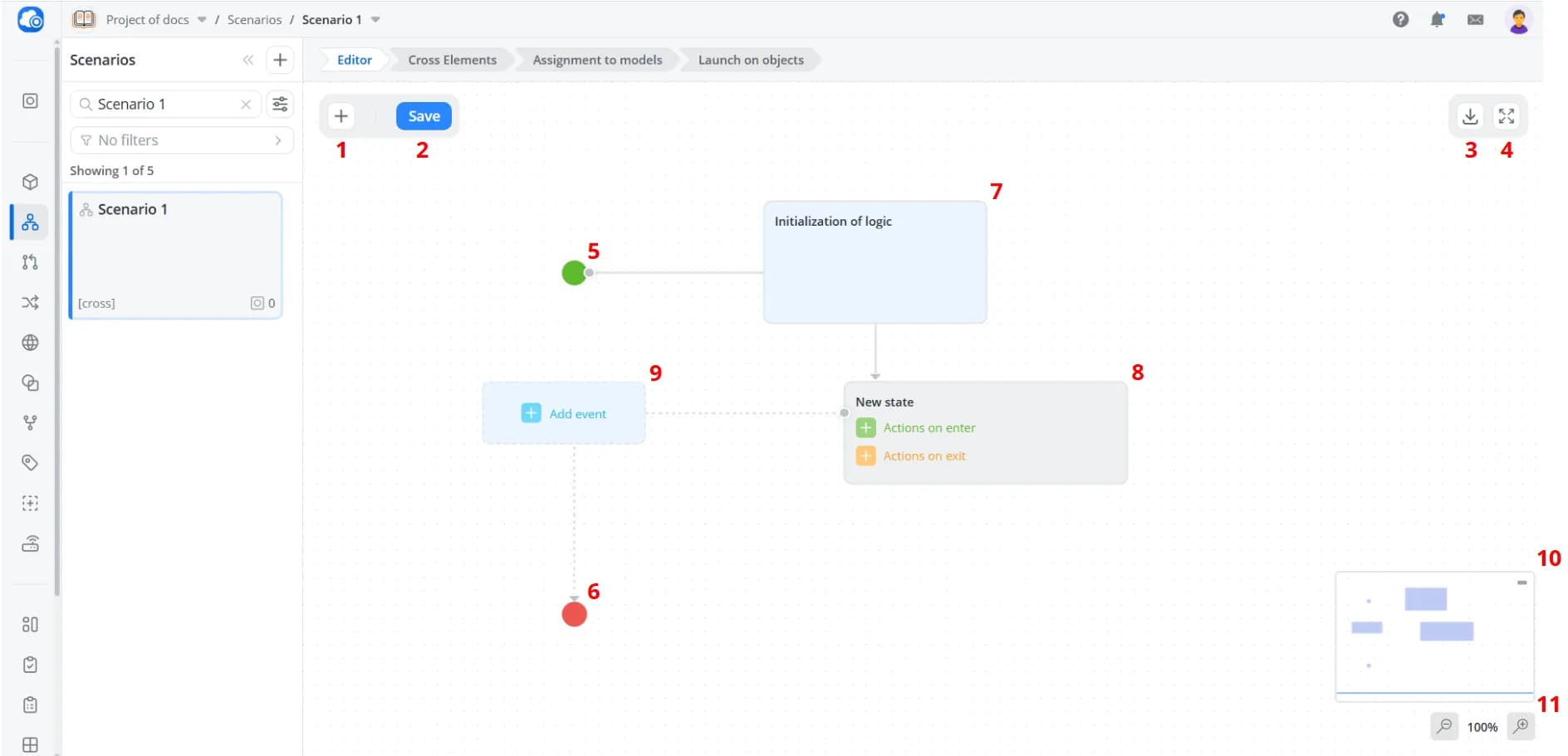
1 – Add state: Adds a new state to the workspace
2 – Save: Saves changes to the scenario. If the scenario is already running on one or more objects, it will continue operating using the previous version. To apply the new changes, the scenario must be restarted on the object
3 – Export: Exports the scenario as a JSON file
4 – Fullscreen: Opens the workspace in fullscreen mode. All scenario controls remain available while in fullscreen
5 – Initial state: Scenario start marker that indicates the starting point of scenario execution. Present in every scenario
6 – Final state: Scenario end marker that indicates the end of scenario execution. This element may be omitted if the scenario is designed to run continuously in a loop without a defined endpoint
7 – Initialization of logic: The event at the start of interpretation of logic model. Present in every scenario
8 – State: Defines the actions that should be executed when entering and leaving the state
9 – Transition: Defines the event (required) and condition (optional) that trigger a transition from one state to another
10 – Minimap: A small navigation panel that displays the entire scenario. You can navigate either by using the minimap or by moving directly around the workspace. The minimap can be hidden using the button in its upper-right corner
11 – Zoom controls: Buttons for adjusting the workspace zoom level
💡
-
Save your scenario regularly. You can do this by clicking Save or using the keyboard shortcut Ctrl+S.
-
Unsaved changes are preserved when navigating between sections of the platform interface. However, they will be lost if you reload or close the page.
-
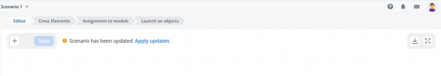
If you have a scenario open, and it is modified from another browser tab, another browser session, or by another user, you will see the message Scenario has been updated along with a button to refresh the data. If you have unsaved changes at that moment, they cannot be saved after the scenario has been updated.
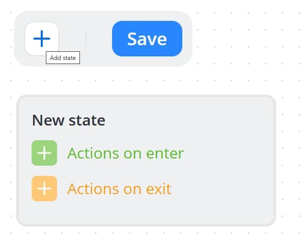
Adding a State
To add a state, click Add state.
State interface
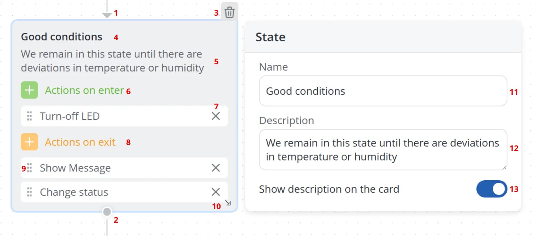
1 – State entry point
2 – State exit point
3 – Deleting state
4 – State name
5 – State description. Displayed only when Show description on the card is enabled
6 – Adding actions to be executed when entering a state. All selected actions are listed below
7 – Removing a selected action
8 – Adding actions to be executed when leaving a state. All selected actions are listed below
9 – Reordering actions using drag-and-drop
10 – Resizing the state block
11 – State name
12 – Description displayed on the state card
13 – Toggle for showing or hiding the description on the state card
Actions in states
To add an action to a state, first determine when it should be executed: on entry or on exit. Then click the
corresponding button to open the full list of available actions. This list contains universal commands available in
every automation scenario.
From the dropdown list, select one or more actions that should be executed when entering or leaving the state.
💡
Actions assigned to state entry are executed whenever the scenario transitions into that state from any other state.
Actions assigned to state exit are executed whenever the scenario transitions from that state to any other state.
Actions assigned to state exit are executed whenever the scenario transitions from that state to any other state.
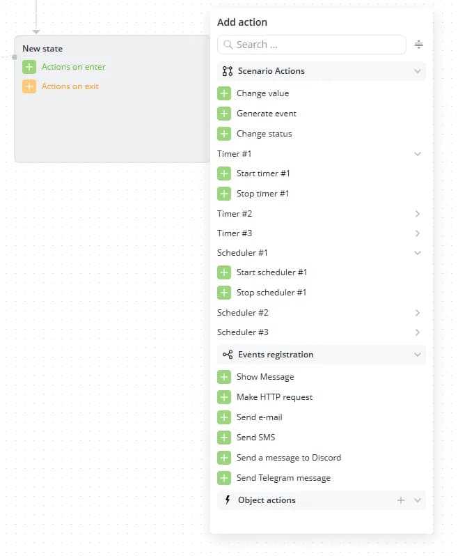
Actions are grouped into three categories:
- Scenario actions — basic actions available in any scenario:
- Change value
- Generate event
- Change status
- Timer #... — timer control commands:
- Start timer #...
- Stop timer #...
- Scheduler #... — scheduler control commands:
- Start scheduler #...
- Stop scheduler #...
- Event registration — actions used to record state entry and exit events:
- Object actions — commands created within the scenario as cross-elements. This category remains empty until you create cross-elements of type Action inside the scenario.
💡
Each action can be added only once for state entry and once for state exit. For example, if you need to send the same
message, e-mail, SMS, or command twice in succession, create an additional state, add the required action there, and
connect the states with an immediate transition. This allows you to repeat the same action multiple times.
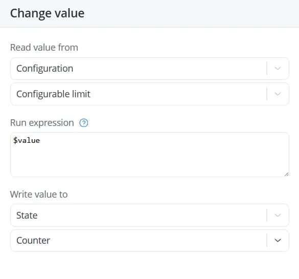
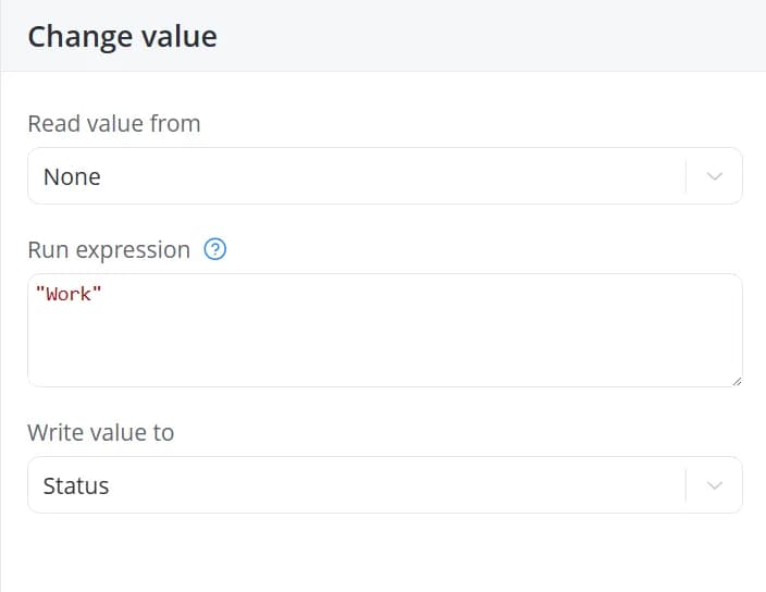
Change value
If the scenario needs to change or set the value of any state, configuration,
or status parameters created in cross-elements, use the Change value action.
This action supports the following operations:
- read a value from a configuration, state, or status parameter and write it unchanged to another configuration, state,
or status parameter. The retrieved value is available as the variable
$value;
💡
When a value is changed in the object's state data, only the visual representation of that parameter in the object
interface is updated. No changes are automatically sent to the connected device.
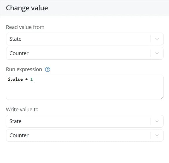
- read a value from a configuration, state, or status parameter, run an expression to it, and write the result to
another configuration, state, or status parameter. Simple arithmetic operations are supported:
+,-,*,/;
- set a specific value within an expression and write it to a configuration, state, or status parameter.
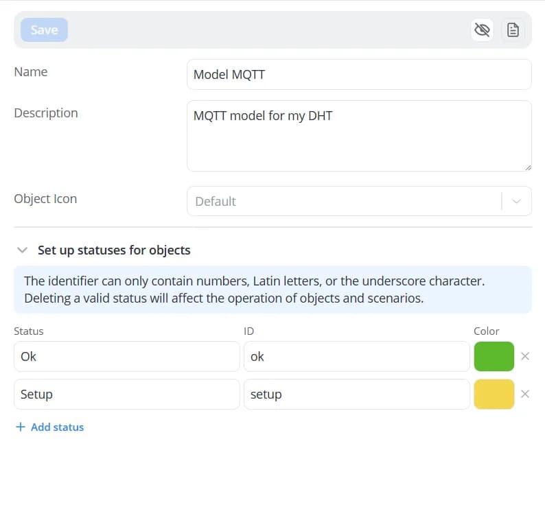
When changing a status value, enter the status name in the Run expression field. The status name must match one
of the statuses defined in the object's model.
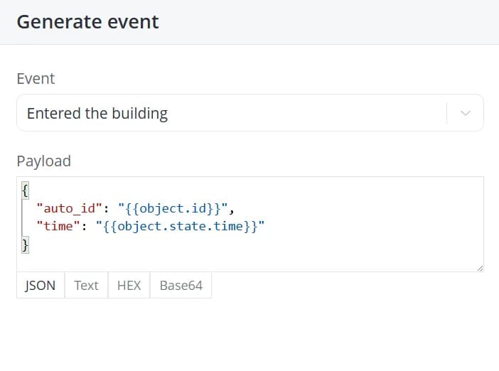
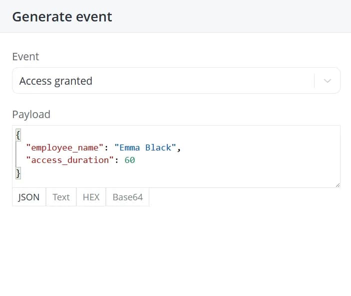
Generate event
To generate an event created as a cross-element, add the Generate event action.
Fill in the following fields:
- Event — select the event created in the cross-elements;
- Payload — you can also specify additional details about the event and process them if it is expected that the event is also received by an external system connected via WebSocket.
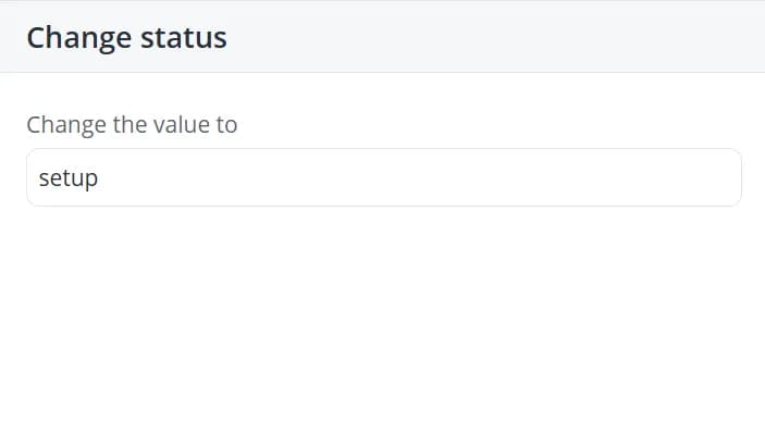
Change Status
The Change status action is a specialized form of the Change value action that allows you to change the status
of the object on which the scenario is running. To do this, enter the status identifier in the Change value field.
The specified identifier must match one of the available statuses defined in the object's model.
Start/stop timer #...
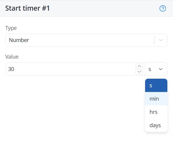
Starting a timer allows you to trigger an event after a specified period of time has elapsed. To configure a timer, add
the Start timer action to a state. A configuration panel will appear on the right, where you can specify the timer
value using one of the following types:
- Number – enter a Value representing the number of seconds, minutes, hours, or days after which the timer should trigger;
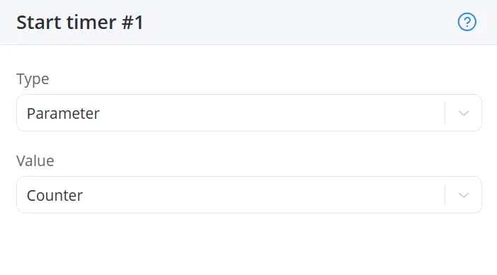
- Parameter – select a parameter created in the cross-elements section. The value of that parameter will be used as the timer duration;
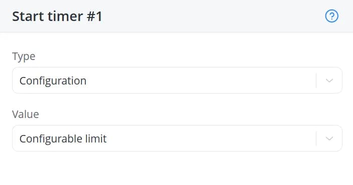
- Configuration – select a configuration parameter created in the cross-elements section. Its value will be used as the timer duration.
When the specified time interval expires, a Timer triggered event is generated. This event can then be used in transitions.
The timer's operation, like that of the scheduler, applies to the entire scenario, not just the state in
which it was launched. This means that once started, a timer will continue running regardless of which state the
scenario is currently in. The timer will trigger even if the scenario has already transitioned to a different state.
The Stop timer action stops a running timer.
Start/stop scheduler #...
Starting a scheduler allows you to generate an event at specific dates and times. To configure a scheduler, add the
Start scheduler action to a state. A configuration panel will appear on the right. Fill in the following fields:
-
Time zone – is set by default to the time zone configured in your platform account, but can be changed;
-
Type:
-
Simple – select only the day of the week;
-
Extended – select the month, day of the week, and day of the month;
-
-
Month (if extended);
-
Day of week;
-
Day of month (if extended).
| Simple | Extended |
|---|---|
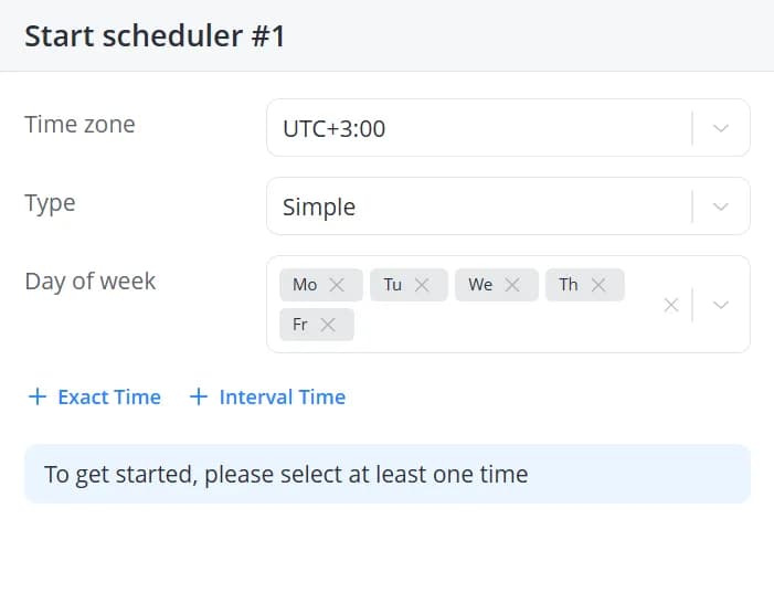 | 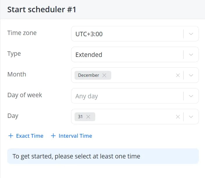 |
Next, configure the trigger time. Exact-time and interval-based schedules are configured independently and operate
simultaneously:
-
Exact Time – the scheduler triggers at a specific time. For example, if you set 13:15, the Scheduler triggered event will occur exactly at 13:15:00.
-
Interval Time – allows you to define a time range and a repetition interval within that range. For example, if you select a range from 13:00 to 14:00 with an interval of Every 2 minutes, the scheduler will trigger at 13:00:00, 13:02:00, 13:04:00, and so on.
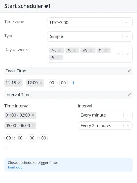
To check the next scheduled execution time, click Find out. This is particularly useful for validating
complex scheduler configurations.
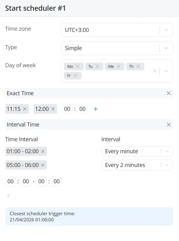
Each time the current date and time match the scheduler pattern, a Scheduler triggered event is generated. This
event can be used in state transitions.
The scheduler's operation, like that of the timer, applies to the entire scenario, not just the state in
which it was launched. This means that once started, a scheduler will continue running regardless of which state the
scenario is currently in. The scheduler will trigger even if the scenario has already transitioned to a different state.
The Stop scheduler action stops a running scheduler.
Show message
Messages can be used to track changes that occur during the execution of a scenario. If you add the Show message
action to a state's entry actions, the system will generate a notification whenever the object enters that state. The
notification can be used to indicate that a specific event has occurred and that the object has transitioned into the
corresponding state.
Creating messages
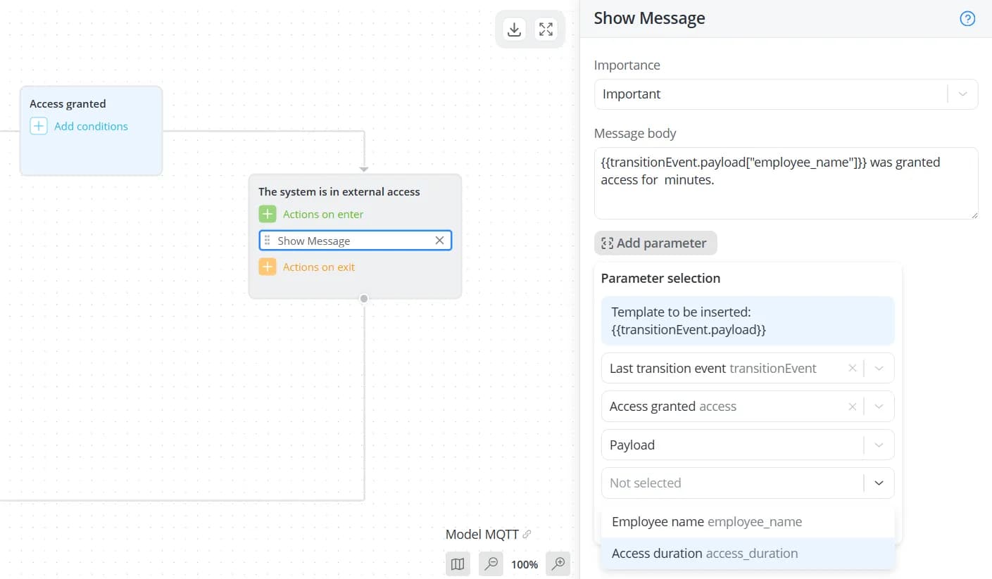
To create a message, add the Show message action to a state. A configuration panel will appear on the right, where
you can select the message importance level:
- Informational;
- Important;
- Critical;
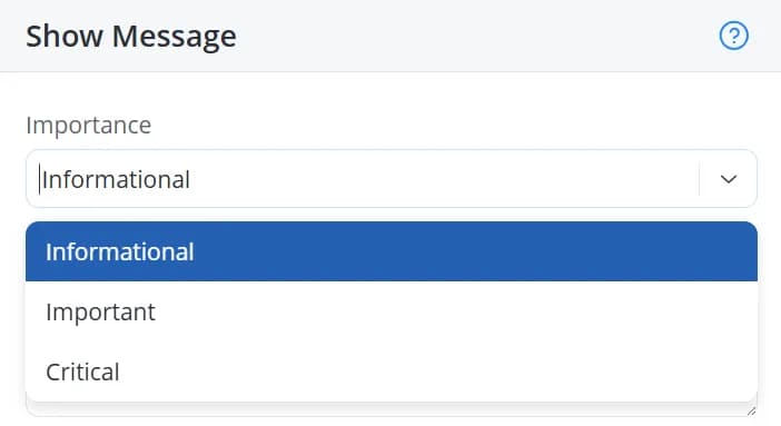
If the message is intended to indicate that an event or transition has occurred, the Informational level is usually
sufficient. For more significant situations, such as abnormal conditions or rule violations, it is recommended to use a
higher severity level.
💡
For Critical messages, additional notification options can be enabled in
the Profile section.
Next, enter the message content. The message format is completely flexible and is not restricted by any predefined
structure. However, it is recommended that it be brief and informative to ensure it displays properly on the platform.
In addition to descriptive text, you can include dynamic parameter values in the message. To do this, click Add
parameter and select the parameters whose values should be inserted into the message.
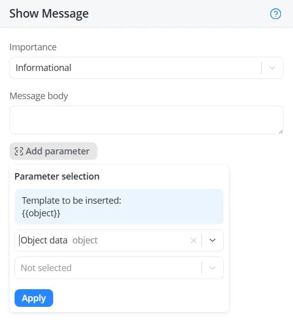
Depending on the nesting level of the selected parameter, additional dropdown lists may appear. When working with a
large number of cross-elements, you can use the search field to quickly locate the required parameter.
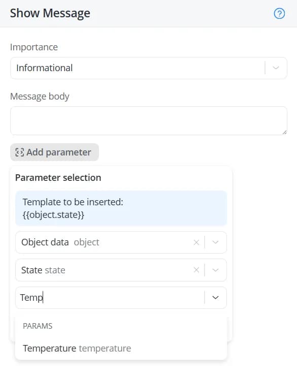
After selecting the required parameter, click Apply. After that, you will see that the message text will include
a statement with a parameter enclosed in curly braces, for example
{{object.state["humidity"]}}, {{object.name}} and
so on.In that case, the message could be formatted as follows, for example:
{
  "event": "Good conditions",
  "temperature": {{object.state["temperature"]}}
}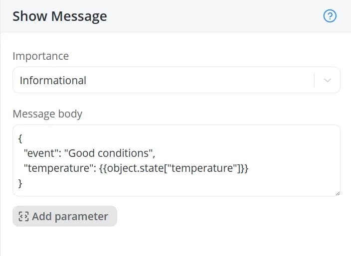
When the message is generated, the statement
{{object.state["temperature"]}} will be replaced with the current value
of the parameter associated with the cross-element whose identifier is temperature.
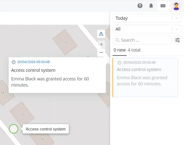
Viewing messages
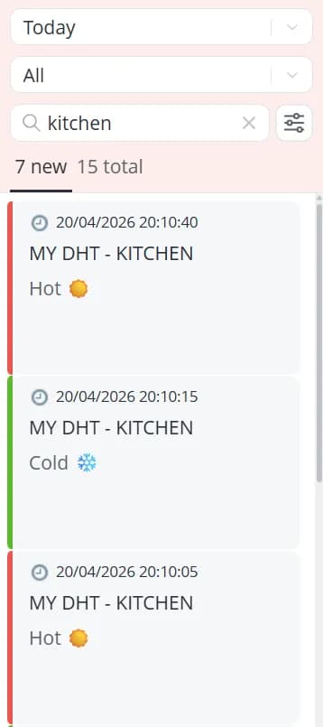
Generated messages are displayed in the message panel located on the right side of the interface.

1 – Button for opening and closing the message panel. When unread messages are present, the button is displayed as follows:

2 – Filter by time received. Messages can be displayed for the following time periods: Last hour, Today,
Yesterday, and Last 7 days. You can also specify a custom time range by clicking Select period. Please note
that the interval between the start and end of the period may not exceed 30 days
3 – Severity filter. Messages can be filtered by Critical, Important, or Informational level. Each priority level is identified by a specific color: red, yellow, or green, respectively
4 – Message grouping selector. Messages can be grouped by object name or by message
5 – Search field for finding messages by object name or message
6 – Number of unread messages and the total number of messages received during the selected period, that match the currently applied filters
7 – Date and time when the message was received
8 – Name of the object associated with the message
9 – Message content
10 – Clicking a message expands it in the panel area to the left, marks it as read, and removes it from the unread list
11 – Message timestamp. Click it to open the object's history and navigate directly to the data packet received at that time. If no data was received at that exact moment, the first data packet available for Today will be displayed instead
12 – Clearing the list of unread messages that match the currently applied filters
💡
If new messages arrive that do not match the currently applied filters or search criteria, the configurable section of
the message panel is briefly highlighted in red.
Available grouping options:
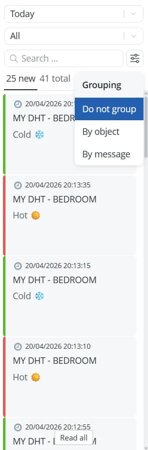
- Do not group – no grouping, messages are displayed as a complete list;
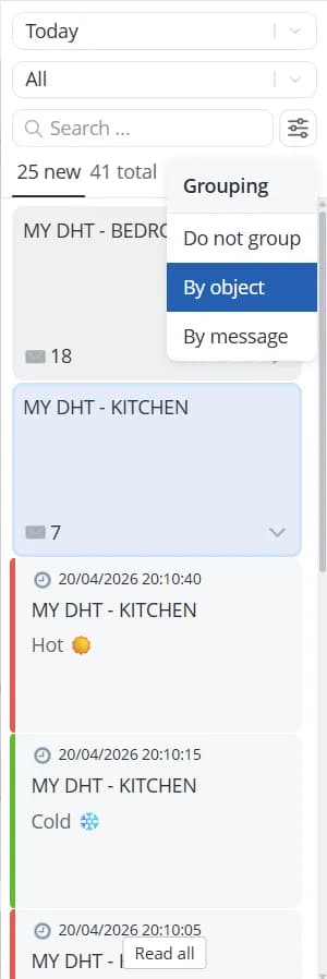
- By object – for each object, all messages will be grouped together. The number of messages in the group is displayed in the lower-left corner of the group card;
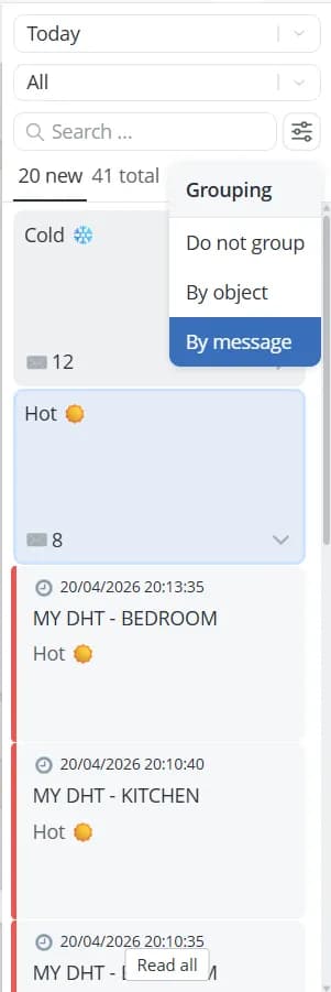
- By message – messages with the same text are grouped together. The number of messages in the group is displayed in the lower-left corner of the group card;
💡
If an object is deleted, messages previously received for that object will remain available in the message list.
However, the object name will be replaced with a question mark. Click a message to expand it and view its contents. The
identifier of the deleted object will still be available, allowing you to get its
messages through the API if necessary.

Make HTTP request
If your scenario needs to send data or get data from an external service — such as a mobile or web application,
CRM, ERP system, or any other third-party platform — you can use the Make HTTP request action. This action allows
the scenario to exchange data with external systems using the HTTP protocol.
💡
HTTP requests are rate-limited to one request per second per object.
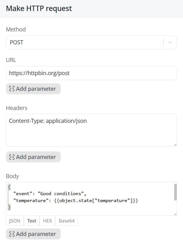
To configure an HTTP request, add the Make HTTP request action to a state. A configuration panel will appear on the
right. Fill in the following fields:
-
Method – the HTTP request method:
-
GET – get data from the specified resource;
-
POST – send data to a resource;
-
PUT – replace an entire resource with the provided data;
-
PATCH – similar to PUT, but updates only a specific portion of the resource;
-
DELETE – remove data from a resource;
-
-
URL – the destination URL to which the request will be sent;
-
Headers – additional metadata used to define how the request should be processed by the server. Headers can be used to specify authentication parameters, content language, request and response formats, connection settings, and other protocol-specific options;
-
Body – the data payload to send with the request. This field is optional.
For example, you can send HTTP requests from a scenario to Telegram using the official Telegram API.
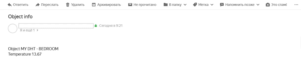
Send e-mail
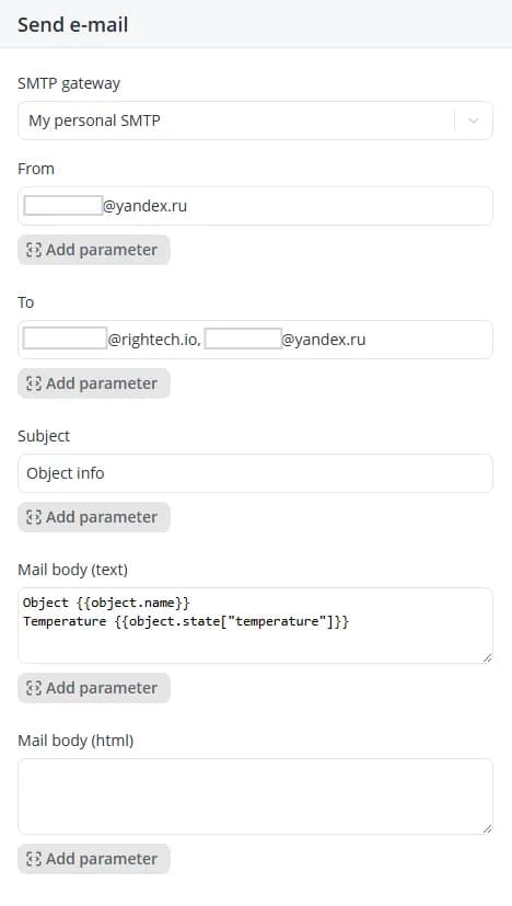
If your scenario needs to send email notifications to specific recipients, use the Send e-mail action. To configure
email delivery, add the Send e-mail action to a state. A configuration panel will appear on the right, where you can
specify the following settings:
-
SMTP gateway (required) – the outgoing mail server that will be used to send the email via the SMTP protocol. Learn more about configuring an SMTP server >>>
-
From (required) – the email address that the message will be sent from;
-
To (required) – one or more email addresses that will receive the message. Multiple addresses can be specified as a comma-separated list;
-
Subject (required) – the email subject line;
-
Mail body (text) – the plain-text version of the message body;
-
Mail body (html) – the message body in HTML format. If this field is populated, the Mail body (text) field is ignored.
Send SMS
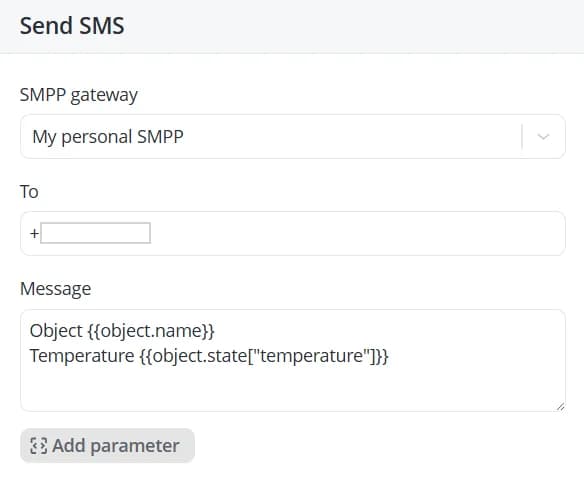
If your scenario needs to send SMS messages to specific phone numbers, use the Send SMS action. To configure SMS
delivery, add the Send SMS action to a state. A configuration panel will appear on the right, where you can specify
the following settings:
-
SMPP gateway (required) – the SMS gateway server used to send messages via the SMPP protocol;
-
To (required) – one or more phone numbers that will receive the message. Multiple numbers can be specified as a comma-separated list;
-
Message – the content of the SMS message.
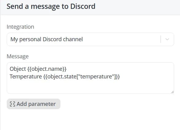
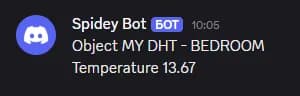
Send Discord message
If your scenario needs to send messages to a specific Discord channel via a webhook, use the Send Discord message
action. Add an action to the state — a sidebar will appear on the right. Fill in the following fields:
-
Integration (required) – the Discord webhook to use for message delivery. Learn more about configuring a Discord integration >>>
-
Message – the content of the message to send.
Send Telegram message
If your scenario needs to send messages to Telegram — whether to a group, channel, or directly to a user — use
the Send Telegram message action.
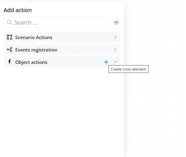
Action-type cross-elements
Any command defined in an object model can be executed from a scenario. To create an action-type cross-element, click
the plus button in the Object actions section of the available actions list for a state.
A configuration panel will appear on the right. Fill in the following fields:
-
Type – automatically set to Action and cannot be changed;
-
ID – an identifier used internally by the system to reference the cross-element. It must be unique within the current scenario;
-
Name – the display name of the action;
-
Description – an optional description that provides additional information about the action.
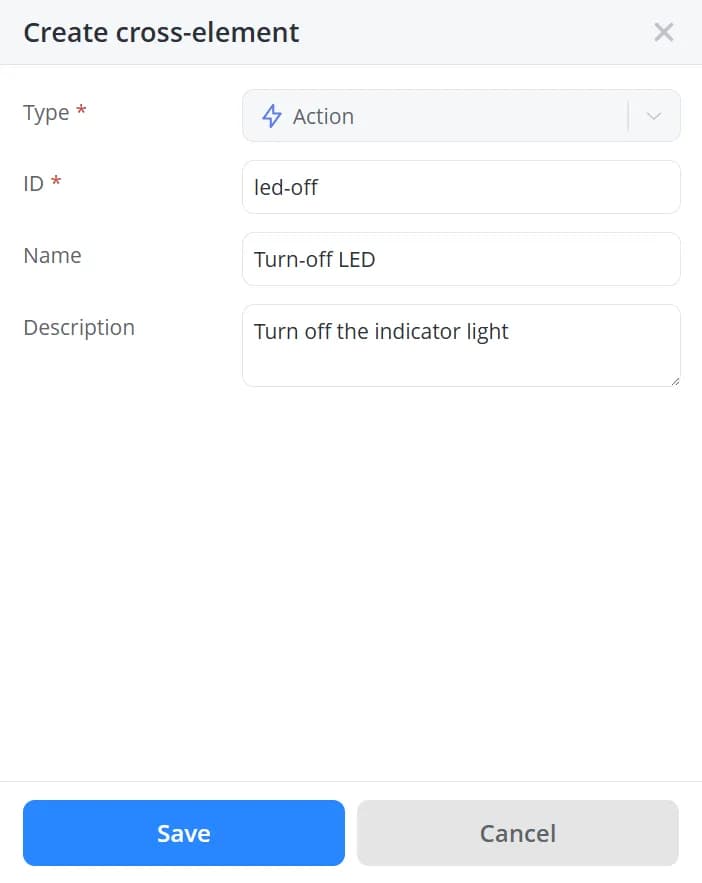
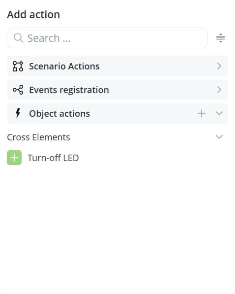
Click Save. The new action will appear in the list of available actions.
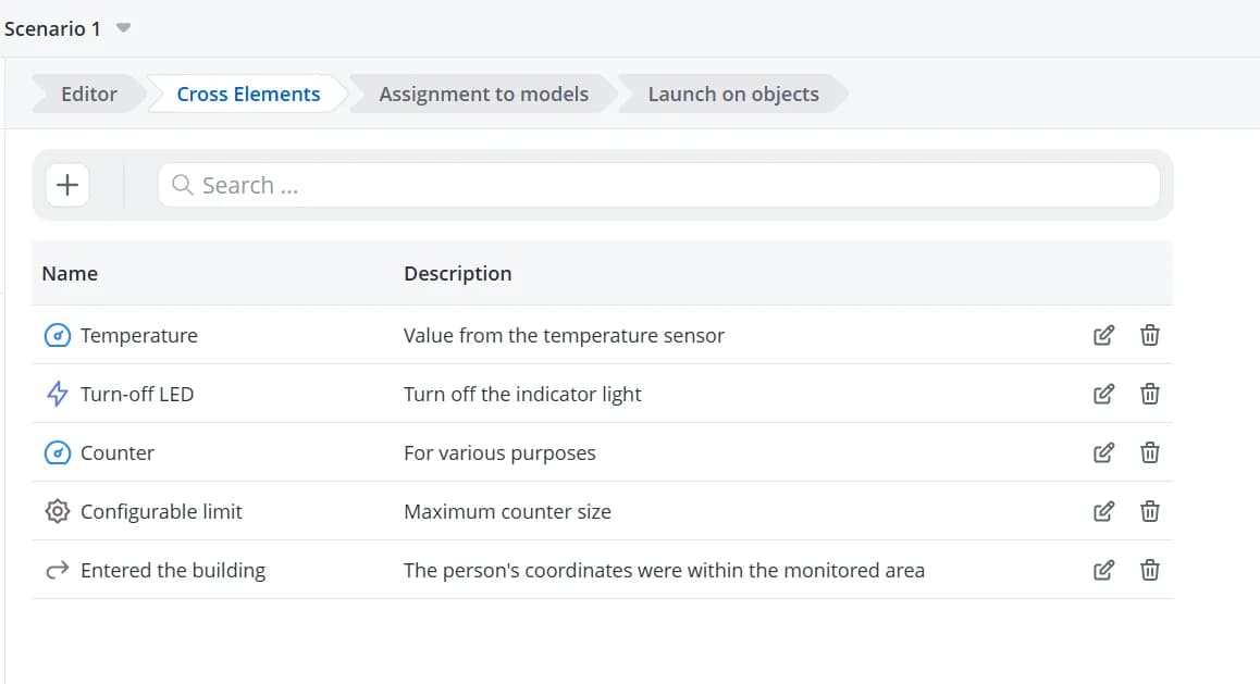
To modify an existing action, open the Cross-elements tab. This tab displays all cross-elements created within the
current scenario. From there, you can edit, delete, or create cross-elements.

💡
Because cross-elements are created as generic, model-independent abstractions, they do not take into account any
additional settings that may be configured in the corresponding model action, such as confirmation requirements or
custom input parameters. As a result, commands that require user confirmation before execution or additional parameters
cannot be executed from scenarios built using cross-elements. To execute commands that require confirmation or accept
additional parameters, use actions in scenarios of the By parameters from model type.
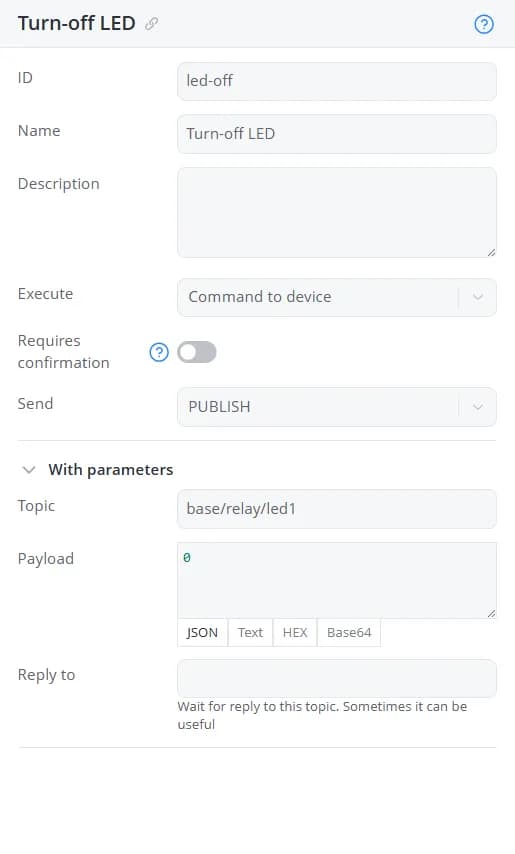
Model commands
Any command defined in an object model can be executed from a scenario of the By parameters from model type. To do
this, add the required command to the state. A configuration panel will appear, displaying detailed information about
the selected command. A shortcut link is available next to the command name, allowing you to quickly navigate to the
corresponding item in the model tree. Use this link if you need to modify the command configuration.
If the command has the Requires confirmation option enabled, a warning will be displayed in the configuration panel,
along with the Allow sending with confirmation from scenario toggle. Enable this option if you want the
command to be executed from the scenario.
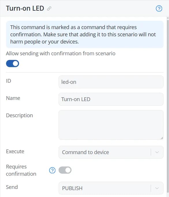
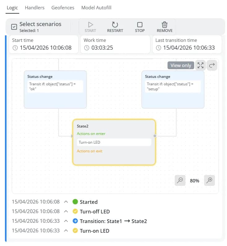
When enabled, the command will be executed by the scenario without requiring any additional user confirmation.
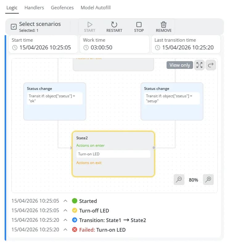
If the toggle remains disabled, the action will be highlighted with a red border in the scenario editor.

While the scenario is running, commands marked in this way will not be sent.
Scenarios built using model parameters can also execute commands that require input parameters to be specified before
they are sent.
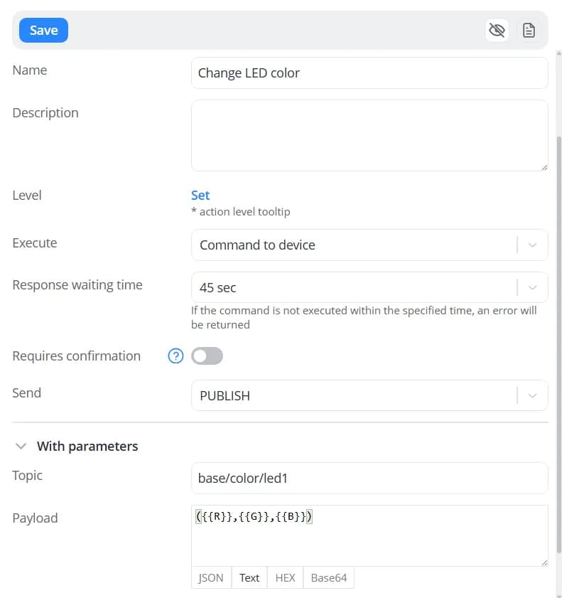
When adding such a command, enter the required parameter values in the action configuration form.

The same command can be used in multiple states, either with the same parameter values or with different values for each state.

Creating a transition
To create a transition between two states, drag a dashed connection line from the edge of the source state to the edge
of the destination state.
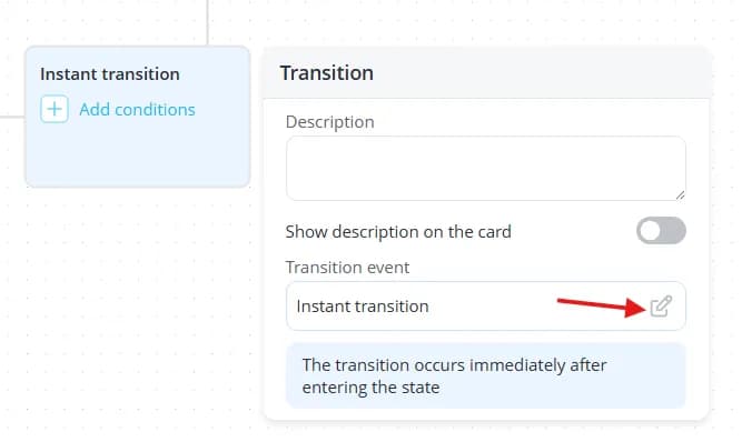
Transition event interface
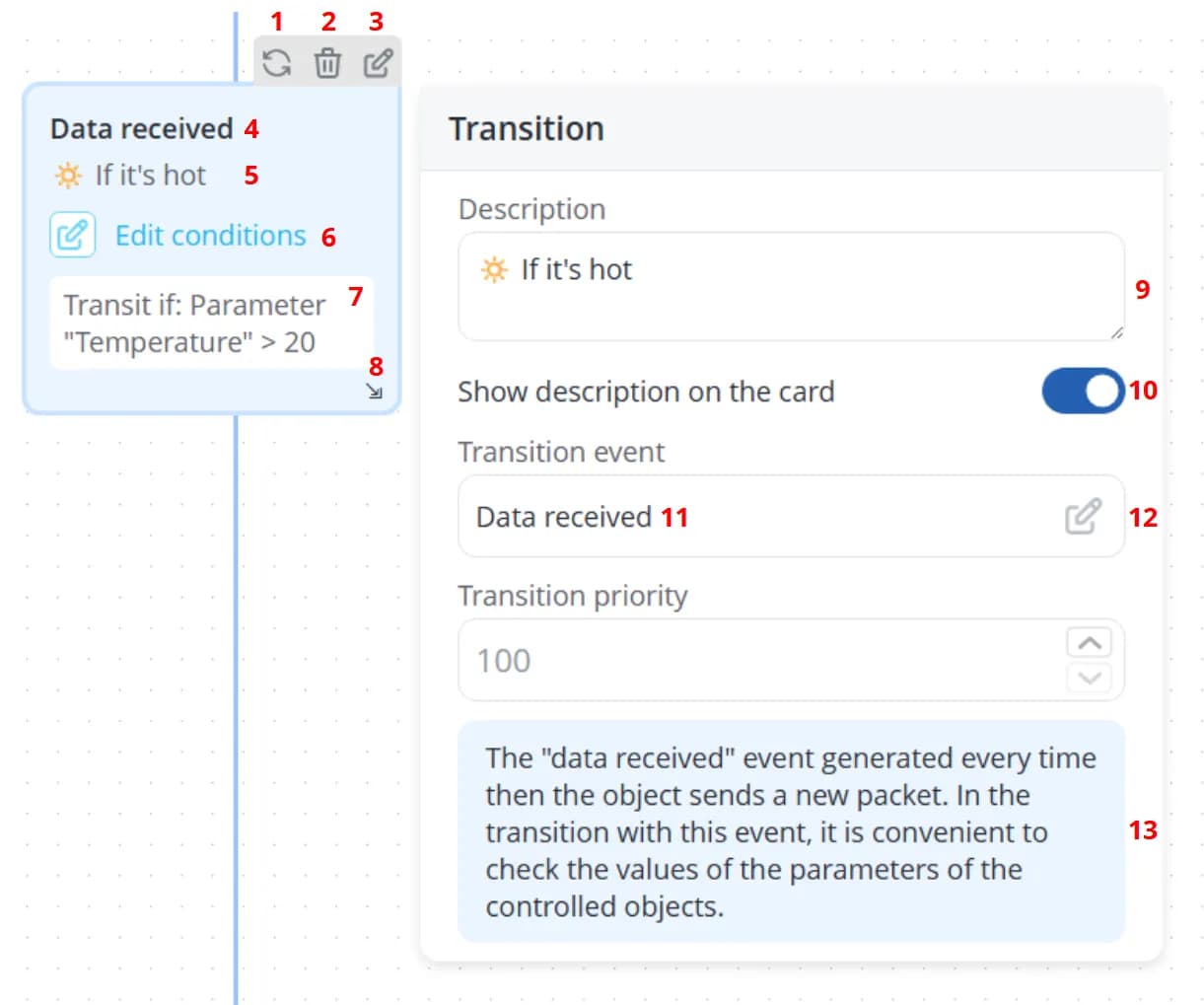
1 – Align the transition between states
2 – Delete the transition
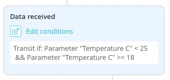
3 – Edit transition conditions. This button becomes available after an event has been assigned to the transition. If no conditions have been added yet, the button is labeled Add conditions instead of Edit conditions
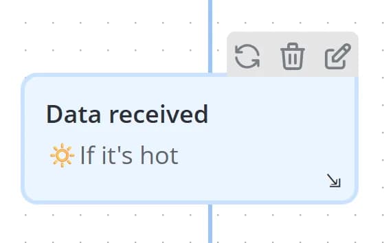
4 – Event name
5 – Transition description. Displayed only when Show description on the card is enabled
6 – Edit transition conditions. If no conditions have been added yet, the button is labeled Add conditions instead of Edit conditions
7 – Condition summary. This text is generated automatically based on the configured conditions
8 – Resize the transition card
9 – Description displayed on the transition card
10 – Toggle for showing or hiding the description on the transition card
11 – Name of the event assigned to the transition
12 – Change the transition event
13 – Description of the selected event
2 – Delete the transition
3 – Edit transition conditions. This button becomes available after an event has been assigned to the transition. If no conditions have been added yet, the button is labeled Add conditions instead of Edit conditions
4 – Event name
5 – Transition description. Displayed only when Show description on the card is enabled
6 – Edit transition conditions. If no conditions have been added yet, the button is labeled Add conditions instead of Edit conditions
7 – Condition summary. This text is generated automatically based on the configured conditions
8 – Resize the transition card
9 – Description displayed on the transition card
10 – Toggle for showing or hiding the description on the transition card
11 – Name of the event assigned to the transition
12 – Change the transition event
13 – Description of the selected event
💡
The Add/Edit Conditions button that appears when hovering over a transition card provides the same functionality as
the corresponding button inside the card. The floating button is particularly useful when the transition card has been
resized to save workspace space, as the controls inside the card may no longer be visible.
Transition condition interface
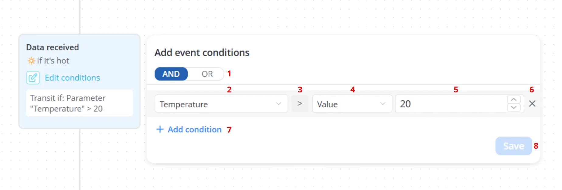
1 – Select how the conditions below should be combined
2 – Parameter to evaluate
3 – Comparison operator
4 – Category that determines what the parameter will be compared against
5 – Depending on the selected category, specify a value, select a level, or choose another parameter
6 – Delete the selected condition
7 – Add a new condition
8 – Save the configured conditions
💡
To pan around the scenario editor, click and hold the mouse wheel (middle mouse button) while moving the mouse.
Events
For each transition, specify the event that must occur in order for the transition to be executed.
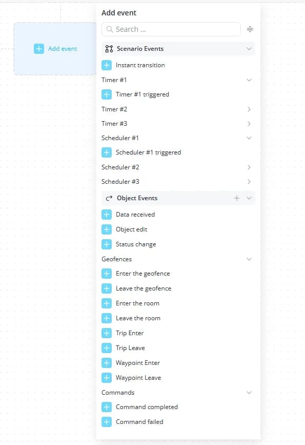
Built-in events
Events that are available in every scenario, regardless of whether any cross-elements have been created, are divided into two categories:
- Scenario Events:
-
Instant transition – the transition is executed as soon as the scenario enters the state from which the transition originates;
-
Timer #... – timer-related events:
- Timer #... triggered – the transition is executed when the corresponding running timer expires;
-
Scheduler #... – scheduler-related events:
- Scheduler #... triggered – the transition is executed when the corresponding running scheduler is triggered.
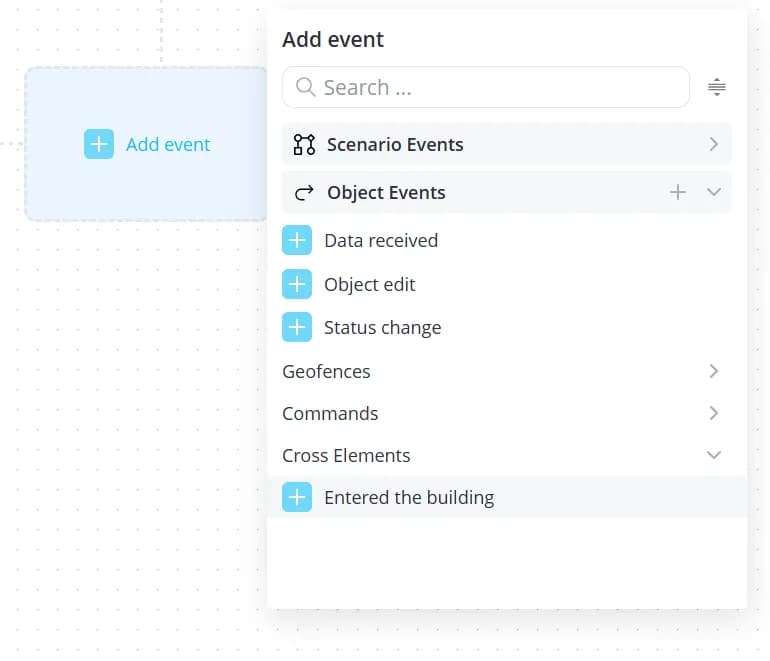
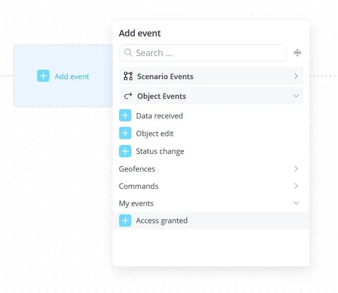
- Object Events:
-
Data received – the transition is executed when a new data packet is received;
-
Object edit – the transition is executed when changes are saved on the object's Edit tab;
-
Status change – the transition is executed when the object's status changes;
-
Geofences – location-based events:
-
Enter the geofence – the transition is executed when the object enters a monitored geofence;
-
Leave the geofence – the transition is executed when the object leaves a monitored geofence;
-
Enter the room – the transition is executed when the object enters a monitored room on a floor plan;
-
Leave the room – the transition is executed when the object leaves a monitored room on a floor plan;
-
Trip Enter – the transition is executed when the object approaches a predefined route to within 50 meters;
-
Trip Leave – the transition is executed when the object moves more than 50 meters away from the predefined route;
-
Waypoint Enter – the transition is executed when the object comes within 50 meters of a route checkpoint;
-
Waypoint Leave – the transition is executed when the object moves more than 50 meters away from a route checkpoint.
-
-
Commands – events related to command execution on the object:
-
Command completed – the transition is executed when the command specified in the transition conditions completes successfully;
-
Command failed – the transition is executed when the command specified in the transition conditions fails. For example, this event may occur if the device does not acknowledge the command according to the communication protocol or loses its connection to the platform.
-
If necessary, the event assigned to a transition can be changed. To do so, click the transition and then click the
change event button. A dropdown list will appear, allowing you to select a different event.
💡
To prevent runaway execution, scenarios include built-in protection against excessive numbers of transitions
occurring within a short period of time. Keep this limitation in mind when designing scenarios that contain loops or
cyclical execution paths.
For example, if a scenario is configured with an endless loop using Instant transition event, execution will
eventually be stopped automatically and the scenario status will change to Emergency stop.
Event-type cross-elements
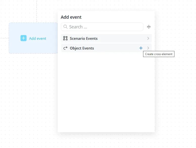
Any event defined in an object model can be used as a trigger in a scenario transition. To create an event-type
cross-element, click the plus button in the Object Events section of the transition event list.
A configuration panel will appear on the right. Fill in the following fields:
-
Type – automatically set to Event and cannot be changed;
-
ID – an identifier used internally by the system to reference the cross-element. It must be unique within the current scenario;
-
Name – the display name of the event;
-
Description – an optional description that provides additional information about the event.
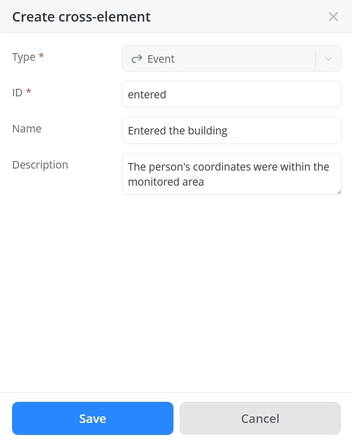
Click Save. The new event will appear in the list of available events.
To modify an existing event, open the Cross-elements tab. This tab displays all cross-elements created within the
current automation scenario. From there, you can edit, delete, or create cross-elements.
💡
When creating a custom event in an object model, you can define event parameters. These parameters can later be passed
when the event is received through the API or generated by another scenario, allowing their values to be used
in event logging and related actions. However, because cross-elements are created as generic, model-independent
abstractions, they do not take into account any additional parameters that may be defined in the corresponding model event.
As a result, scenarios built using cross-elements cannot access or process parameters contained in the received event.
To work with event parameters, use events in scenarios of the By parameters from model type.
Model events
Create a custom event in the model and, if necessary, define additional event parameters.
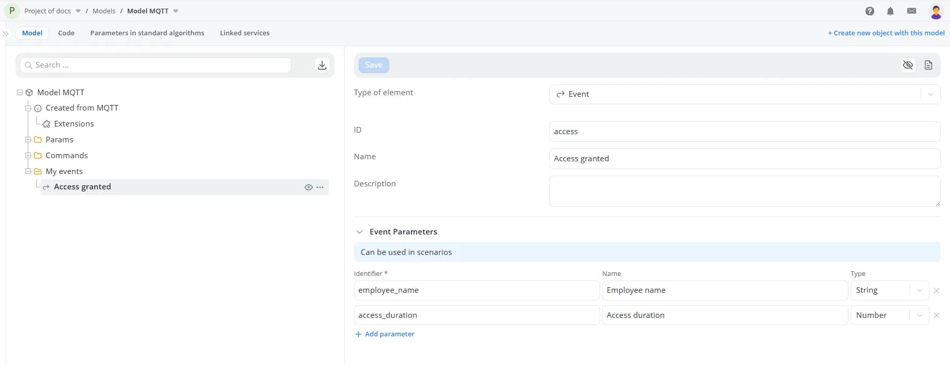
The event will then appear in the list of available transition events.
These events can be received from external systems via the API or generated by other scenarios using the
Generate event action. When generating the event, specify the event parameter values in JSON format.
If a transition in your scenario is triggered by this event, you can use the event's parameter values in
event logging and notification actions within the destination state. To do this, open the appropriate action and click
Add parameter. Then select the Last transition event parameter category and choose the event parameters whose
values you want to include in the message.
💡
Creating an event in the model alone is not sufficient for it to appear in the Last transition event parameter list.
The scenario must actually transition into the target state as a result of that event. Only then will the event data
become available for use within that state's actions.
When the message is generated, the statements will be replaced with the parameter values received as part of the event.
Conditions
After selecting a transition event, you can optionally define one or more conditions that must be satisfied before the
transition is executed.
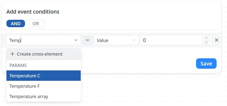
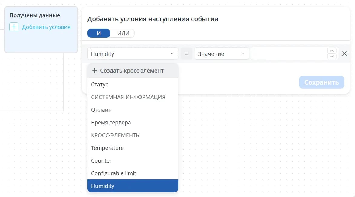
To create a condition, select the parameter whose value should be evaluated from the dropdown list.
💡
When working with a large number of parameters, you can use the search field to quickly find the required parameter.
Parameters can be compared against:
-
a specific value – enter a numeric, string, or boolean value that matches the parameter's data type;
-
another parameter – select a parameter to compare against;
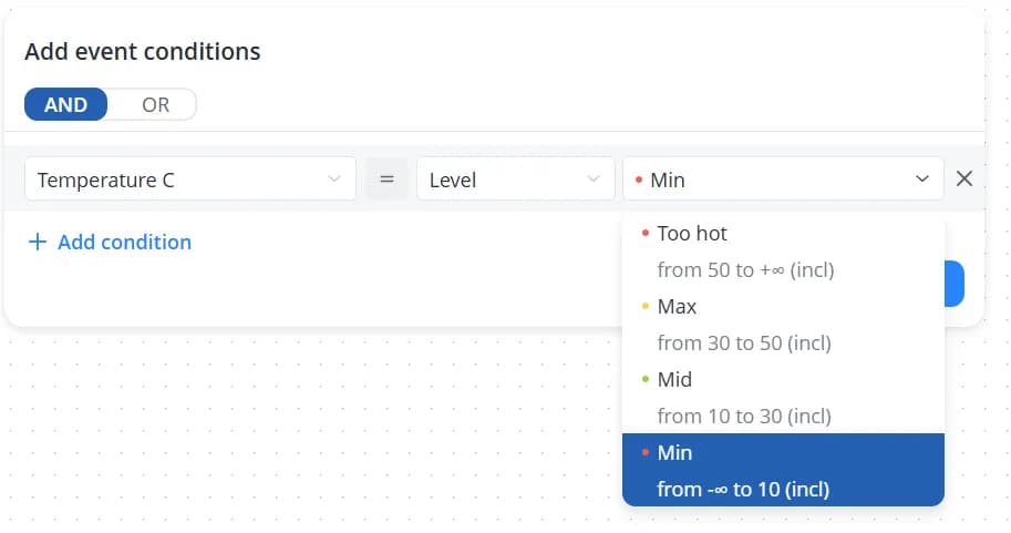
-
a level – select one of the levels defined for the parameter in the object model;
-
a configuration value – select a parameter of type Configuration. Comparing against configuration parameters is useful when the same scenario logic is shared across multiple objects, but the condition thresholds differ. For example, one temperature range may be considered normal for a bedroom, while a different range is appropriate for a kitchen. In this case, there is no need to create separate climate-control scenarios for each room. Instead, you can define configuration parameters that store the acceptable temperature ranges for each object and compare the current temperature against those configuration values rather than hard-coded numbers.
💡
The Level section is available only when the scenario is of type By parameters from model and levels have been
defined in the model for the selected parameter.
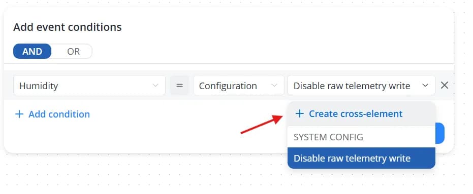
The Configuration section is available only when:
-
the scenario of type By cross-elements contains cross-elements of type Configuration, or
-
the scenario of type By parameters from model contains model nodes of type Configuration.
Select a comparison operator, and after defining the condition, click the Save button.
💡
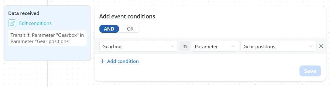
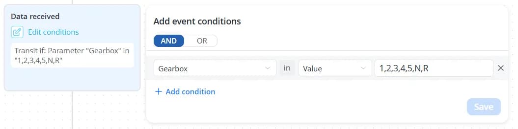
The in operator can be used to:
-
check whether a parameter value exists within an array of values;
-
check whether a string contains a specific substring.
The not in operator  verifies that the selected parameter value is not present in an array
and is not contained within a string.
verifies that the selected parameter value is not present in an array
and is not contained within a string.
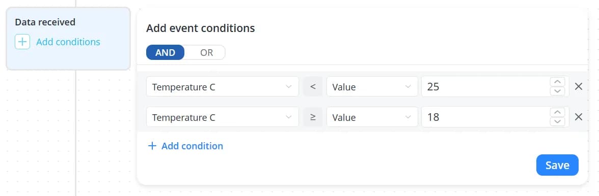
A transition can contain between one and four conditions. Use the AND and OR buttons to define how multiple
conditions should be combined:
-
AND – all conditions must evaluate to true for the transition to occur;
-
OR – at least one condition must evaluate to true for the transition to occur.
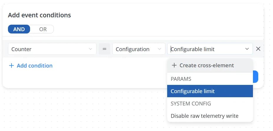
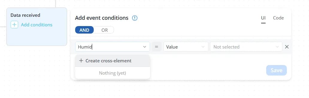
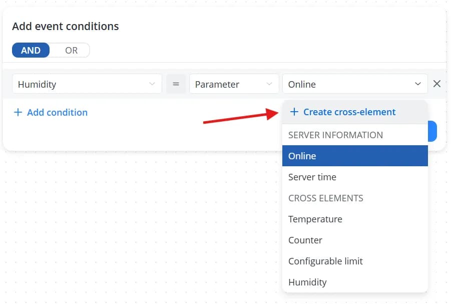
If the required cross-element is not yet available in the parameter list, you can create it directly from the condition
editor. To do so, click Create cross-element.
A configuration panel will appear on the right. Fill in the following fields:
-
Type – automatically set to Parameter and cannot be changed;
-
ID – an identifier used internally by the system to reference the cross-element. It must be unique within the current scenario;
-
Name – the display name of the parameter;
-
Description – an optional description that provides additional information about the parameter;
-
Data type – depending on the parameter's data type, a list of possible comparison operations is generated.
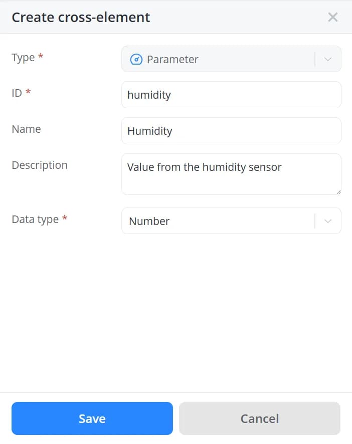
Click Save. The new parameter will appear in the list.
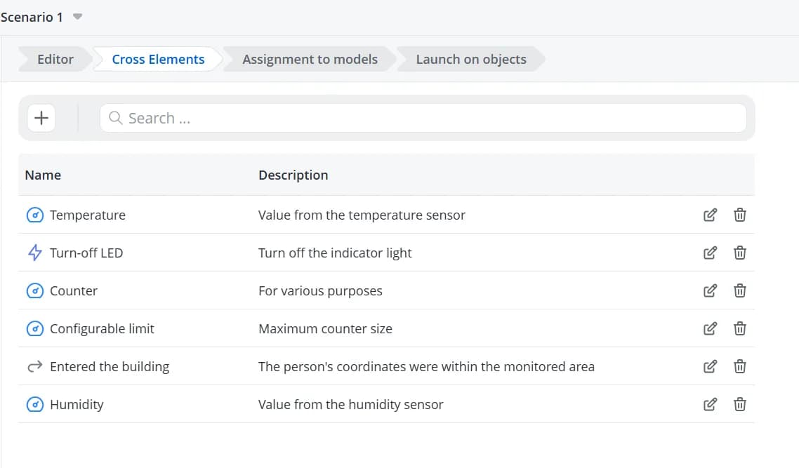
To modify an existing parameter, open the Cross-elements tab. This tab displays all cross-elements created within
the current scenario. From there, you can edit, delete, or create cross-elements.
💡
You can also create cross-elements of type Parameter or Configuration directly while selecting the comparison
value on the right side of the condition editor.
To remove a condition, click the X icon next to it.

Increase the size of the transition card to view the automatically generated description of the configured conditions.